chart

Reduction and Enlargement Percentage Chart

Reduction and Enlargement Percentage Chart

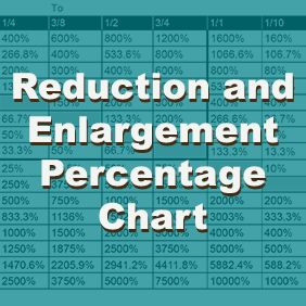
Architecture and engineering. Convert your plans to another scale, without math!

Enlarging plans often means you need a reduction and enlargement percentage chart. I often get asked to enlarge or reduce a plan to a specific scale. For example, an architect may ask me to enlarge a plan that is at 1 foot = 3/32 inch, to 1 foot = 1/4 inch. I deal with a lot of plans. Most of them are architectural, but also mechanical, structural, electrical and plumbing. That’s not all, I also get a lot of engineering, landscaping as well as topographic maps. I have created a reduction and enlargement percentage chart. We can convert these all from PDF to AutoCAD. I also get the dreaded question to convert metric to imperial scale, but I have already covered that.

I work in the reprographics industry, and often have to do this for prints. Sometimes the customer just wants their PDF enlarged, and you can do this by printing to a PDF, and specifying the percentage, and paper size. I hope this architectural scale enlargement chart helps you. Click the chart to download the full size, printable PDF version. Now resize your plans to exact scales using the chart below. Simply match your current scale with the scales on the left, and match it with the scale that you want, and there is your percentage to enlarge or reduce.

Free Enlargement and Reduction Percentage Chart

Free Enlargement and Reduction Percentage Chart
Architecture and Engineering enlargement and reduction chart. Click to download full size PDF

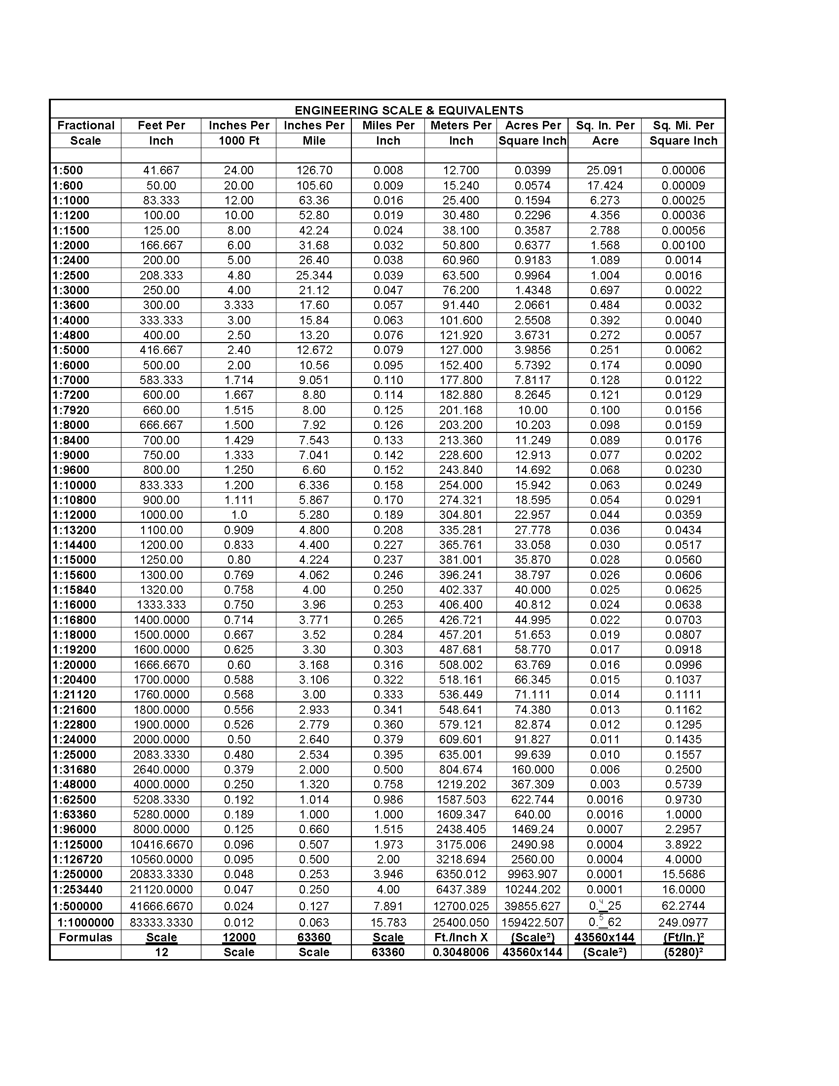
Looking to get your PDF converted to AutoCAD? We will convert your plans to fully layered DWG files. This service is perfect for remodels on as-built plans. For more contact us for a quote for this service. Looking for an AutoCAD scaling factor chart? Bookmark this page, because this chart is very handy for architects, engineers and reprographics / print companies.

Posted by Michael Mellor in AutoCAD tips
Engineering Scales and Equivalents Chart

Engineering Scales and Equivalents Chart

We have a handy PDF file showing engineering and map scales, and their decimal and fractional equivalents. This is an easy to use chart so you can convert to different scales. We have found this useful for converting fractional scale to feet per inch, inches per 1000 feet, inches per mile, meters per inch, acres per square inch, square inches per acre, and square mile per square inch.

Download a printable PDF version of this chart at the link below.

Posted by Michael Mellor
Revit Hotkey and Shortcuts Chart

Shortcut Commands by Category

Here is a list of commands, hotkeys and keyboard shortcuts for the Autodesk 3D design program Revit. If you would like to learn more about Revit and AutoCAD services, contact us.

Annotate

DIALIGNED DIMENSION / Creates an aligned dimension.
DLDETAIL LINE / Creates view-specific lines.
ELSPOT ELEVATION / Displays the elevation of a selected point.
FRFIND/REPLACE / Find and replace.
GPMODEL GROUP:CREATE GROUP; DETAIL GROUP:CREATE GROUP / Creates a group of elements.
RTTAG ROOM; ROOM TAG / Tags the selected room.
TGTAG BY CATEGORY / Applies tags to elements based on their categories.
TXTEXT / Adds text.

Analyze

AAADJUST ANALYTICAL MODEL / Adjusts the analytical model of the structural member in relation to those of the elements to which it joins.
DCCHECK DUCT SYSTEMS / Examines the mechanical systems in a project to verify that each system is assigned to a userdefined system, and properly connected.
ECCHECK CIRCUITS / Verifies all circuits for proper connections to panels and valid system assignments.
LDLOADS / Applies point, line and area loads to a model.
LOHEATING AND COOLING LOADS / Prepares a heating and cooling load analysis report based on an existing building model.
PCCHECK PIPE SYSTEMS / Examines the piping systems in a project to verify that each system is assigned to a user-defined system, and properly connected.
PSPANEL SCHEDULES / Generates a panel schedule for a specific panel.
RARESET ANALYTICAL MODEL / Restores the analytical model alignment methods to auto-detect.

Architecture

CLCOLUMN; STRUCTURAL COLUMN / Adds a vertical load-bearing element to the building model.
CMPLACE A COMPONENT / Place a component.
DRDOOR / Adds a door to the building model.
GRGRID / Places column grid lines in the building design.
LLLEVEL / Places a level in view.
RMROOM / Creates a room bounded by model elements and separation lines.
RPREFERENCE PLANE / Creates a reference plane using drawing tools.
RTTAG ROOM; ROOM TAG / Tags the selected room.
SBFLOOR:FLOOR: STRUCTURAL / Adds structural floors to a building model.
WAWALL; WALL:WALL: ARCHITECTURAL / Creates a non-bearing wall or a structural wall in the building model.
WNWINDOW / Places a window in a wall or skylight in a roof.

Collaborate

EREDITING REQUESTS / Displays a list of usersí requests to borrow elements in worksets, as well as pending requests.
RL or RWRELOAD LATEST / Loads the latest version of the central model.

Context Menu

MPMOVE TO PROJECT / Move the model relative to a shared coordinate system.
R3DEFINE A NEW CENTER OF ROTATION / Relocates center of rotation when rotating elements.
RARESTORE ALL EXCLUDED / Restores all excluded parts and elements.
RBRESTORE EXCLUDED MEMBER / Restores an excluded member.
RCREPEAT LAST COMMAND / Repeats the last command.
SASELECT ALL INSTANCES: IN ENTIRE PROJECT / Selects all of the elements that are similar to the selected element in the current view, or throughout the project.

Contextual Tabs

//DIVIDE SURFACE / Applies a division grid along a surface in a conceptual design.
AAADJUST ANALYTICAL MODEL / Adjusts the analytical model of the structural member in relation to those of the elements to which it joins.
ADATTACH DETAIL GROUP / Creates an attached detail group.
APADD TO GROUP / Adds elements to a group.
BSSTRUCTURAL BEAM SYSTEM; AUTOMATIC BEAM SYSTEM / Creates a layout that is used to control the number and spacing of a series of parallel beams.
CGCANCEL / Cancels an action.
DIALIGNED DIMENSION / Creates an aligned dimension.
EGEDIT GROUP / Edits a group.
ELSPOT ELEVATION / Displays the elevation of a selected point.
EPEDIT PAR / Edits a part element.
EUUNHIDE ELEMENT / Enables a hidden element to appear in view.
EWEDIT WITNESS LINES / Edits a witness line.
FGFINISH / Finishes editing a group.
HTSHOW HELP TOOLTIP / Displays the Help Tooltip.
JPJUSTIFICATION POINTS / Sets a justification point for relocating elements.
JYZOFFSET / Offsets an element in the z direction.
JZSHOW HELP TOOLTIP / Displays the Help Tooltip.
LIMODEL LINE; BOUNDARY LINE; REBAR LINE / Places a new line.
PP or CTRL-1 or VPPROPERTIES; TOGGLE PROPERTIES PALETTE / Toggles the Properties palette.
RARESTORE ALL EXCLUDED / Restores all excluded parts and elements.
RGREMOVE FROM GROUP / Removes elements from a group.
RHTOGGLE REVEAL HIDDEN ELEMENTS MODE / Toggles the Reveal Hidden Elements Mode.
RPREFERENCE PLANE / Creates a reference plane using drawing tools.
UGUNGROUP / Ungroups members of a group.
VUUNHIDE CATEGORY / Enables a hidden category to appear in view.

Create

CMPLACE A COMPONENT / Place a component.
DALIGNED DIMENSION / Creates an aligned dimension.
FRFIND/REPLACE / Find and replace.
GPMODEL GROUP:CREATE GROUP; DETAIL GROUP:CREATE GROUP / Creates a group of elements.
LIMODEL LINE; BOUNDARY LINE; REBAR LINE / Places a new line.
LLLEVEL / Places a level in view.
MDMODIFY / Enters selection mode to select elements to modify.
PP or CTRL-1 or VPPROPERTIES; TOGGLE PROPERTIES PALETTE / Toggles the Properties palette.
RPREFERENCE PLANE / Creates a reference plane using drawing tools.
TXTEXT / Adds text

Manage

ESMEP SETTINGS:ELECTRICAL SETTINGS / Accesses dialog box to specify wiring parameters, voltages definitions, distribution systems, cable tray and conduit settings, and load calculation and circuit numbering settings.
MSMEP SETTINGS:MECHANICAL SETTINGS / Accesses dialog box to configure component sizes, and the behavior and appearance of the mechanical systems.
SUADDITIONAL SETTINGS:SUN SETTINGS / Opens the sun settings dialog box.
UNPROJECT UNITS / Opens the Project Units tool.

Modify

ALALIGN / Aligns one or more elements with selected element.
ARARRAY / Creates a linear or radial array of selected elements.
CO or CCCOPY / Copies selected element(s).
CPCOPE; APPLY COPING / Applies coping to steel beam or columns.
CSCREATE SIMILAR / Creates an element of the same type as the selected element.
DEDELETE / Removes selected element(s) from the building model.
DIALIGNED DIMENSION / Creates an aligned dimension.
DMMIRROR – DRAW AXIS / Reverses the position of a selected model element, using a user-generated line as the mirror axis.
EHHIDE IN VIEW:HIDE ELEMENTS / Hides an element from view.
ELSPOT ELEVATION / Displays the elevation of a selected point.
EODOVERRIDE GRAPHICS IN VIEW:OVERRIDE BY ELEMENT / Changes the graphic display settings for selected elements in the current view.
LIMODEL LINE; BOUNDARY LINE; REBAR LINE / Places a new line.
LWLINEWORK / Overrides the line style of selected line in the active view only.
MAMATCH TYPE PROPERTIES / Opens the Match Type tool to convert one or more elements to match the type assigned to another element.
MMMIRROR – PICK AXIS / Reverses the position of a selected model element, using a selected line as the mirror axis.
MVMOVE / Moves a selected element.
OFOFFSET / Moves a selected model line, detail line, wall, or beam a specified distance perpendicular to its length.
PNPIN / Locks a model element in place.
PP or CTRL-1 or VPPROPERTIES; TOGGLE PROPERTIES PALETTE / Toggles the Properties palette.
PTPAINT / Opens the Paint tool.
RCCOPE:REMOVE COPING / Removes coping.
RESCALE / Resizes the selected element.
ROROTATE / Rotates selected element around an axis.
RPREFERENCE PLANE / Creates a reference plane using drawing tools.
SFSPLIT FACE / Divides the face of an element into regions for application of different materials.
SLSPLIT ELEMENT / Cuts an element (such as a wall or line) at a selected point.
TRTRIM/EXTEND TO CORNER / Trims or extend one or more elements to form a corner.
UPUNPIN / Unpins an element that is locked in position or an element that is driven by its host system.
VHHIDE IN VIEW:HIDE CATEGORY / Hides an element category from view.

Navigation Bar

322D MODE / Navigates the view using only 2D navigation options.
3FFLY MODE / Simulates flying through a model.
3OOBJECT MODE / Navigates and reorients the view in the direction of the controller cap.
3WWALK MODE / Simulates walking through a model.
ZAZOOM ALL TO FIT / Zooms to fit all in view.
ZE or ZF or ZXZOOM TO FIT / Zooms to fit.
ZO or ZVZOOM OUT(2X) / Zooms out the project view by 2X.
ZP or ZCPREVIOUS PAN/ZOOM / Returns to previous pan or zoom.l
ZR or ZZZOOM IN REGION / Zooms to a region.
ZSZOOM SHEET SIZE / Zooms to sheet size.

Snaps

PCSNAP TO POINT CLOUDS / Snaps to point cloud.
SCCENTERS / Snaps to center
SEENDPOINTS / Snaps to endpoints.
SIINTERSECTIONS / Snaps to intersection.
SMMIDPOINTS / Snaps to midpoint.
SNNEAREST / Snaps to nearest.
SOSNAPS OFF / Turns snaps off.
SPPERPENDICULAR / Snaps to perpendicular.
SQQUADRANTS / Snaps to quadrant.
SRSNAP TO REMOTE OBJECTS / Snaps to objects that are not near the element.
SSTURN OVERRIDE OFF / Turns off override feature.
STTANGENTS / Snaps to tangent.
SWWORK PLANE GRID / Snaps to the work plane grid.
SXPOINTS / Snaps to points.

Structure

BMSTRUCTURAL FRAMING: BEAM / Adds a load-bearing structural beam element to the building model.
BRSTRUCTURAL FRAMING: BRACE / Adds diagonal members that are connected to beams and columns.
BSSTRUCTURAL BEAM SYSTEM; AUTOMATIC BEAM SYSTEM / Creates a layout that is used to control the number and spacing of a series of parallel beams.
CLCOLUMN; STRUCTURAL COLUMN / Adds a vertical load-bearing element to the building model.
CMPLACE A COMPONENT / Place a component.
FTSTRUCTURAL FOUNDATION: WALL / Creates a wall foundation for the building model.
GRGRID / Places column grid lines in the building design.
LLLEVEL / Places a level in view.
RNREINFORCEMENT NUMBERS / Defines or edits numbering sequences by partition for rebar and fabric sheets.
RPREFERENCE PLANE / Creates a reference plane using drawing tools.
SBFLOOR:FLOOR: STRUCTURAL / Adds structural floors to a building model.
WAWALL; WALL:WALL: ARCHITECTURAL / Creates a non-bearing wall or a structural wall in the building model.

System

ATAIR TERMINAL / Places a register, grille or diffuser.
CMPLACE A COMPONENT / Place a component.
CNCONDUIT / Draws a rigid conduit run.
CTCABLE TRAY / Draws a cable tray run.
CVCONVERT TO FLEX DUCT / Converts a section of rigid duct to flexible duct.
DADUCT ACCESSORY / Adds duct accessories, such as dampers, in duct systems.
DFDUCT FITTING / Places duct fittings (elbows, tees, end caps, and so on) in duct systems.
DTDUCT / Draws ductwork in the building model.
EEELECTRICAL EQUIPMENT / Places electrical equipment, such as panels and switch gear.
EWARC WIRE / Draws an arced wire run.
FDFLEX DUCT / Draws flexible ductwork in the building model.
FPFLEX PIPE / Draws flexible pipes.
LFLIGHTING FIXTURE / Adds a lighting fixture element.
MEMECHANICAL EQUIPMENT / Places mechanical equipment such as boilers, furnaces or fans.
NFCONDUIT FITTING / Places conduit fittings.
PAPIPE ACCESSORY / Adds pipe accessories.
PFPIPE FITTING / Draws a pipe fitting in a piping system.
PIPIPE / Draws rigid piping.
PXPLUMBING FIXTURE / Places a plumbing fixture.
RPREFERENCE PLANE / Creates a reference plane using drawing tools.
SKSPRINKLER / Places a sprinkler
TFCABLE TRAY FITTING / Places cable tray fittings.

View

FN9SYSTEM BROWSER / Finds components that are not assigned to a system.
KSKEYBOARD SHORTCUTS / Assigns key sequences to tools.
PP or CTRL-1 or VPPROPERTIES; TOGGLE PROPERTIES PALETTE / Toggles the Properties palette.
RDRENDER IN CLOUD / Renders 3D views online.
RGRENDER GALLERY / Enables access to multiple versions of renderings, render images as panoramas, change rendering quality, and apply background environments to rendered scenes.
RRRENDER / Creates a photorealistic image of the building model.
TLTHIN LINES / Displays all lines on the screen as a single width, regardless of zoom level.
VG or VVVISIBILITY/GRAPHICS / Controls the visibility and graphic display of model elements, datum elements, and viewspecific elements for each view in a project.
WCCASCADE WINDOWS / Arranges all open windows in a series in the drawing area.
WTTILE WINDOWS / See all open views at the same time.

View Control Bar

CXTOGGLE REVEAL CONSTRAINTS MODE / Toggles the constraints in a view.
GDGRAPHIC DISPLAY OPTIONS / Opens the Graphics dialog box.
HCHIDE CATEGORY / Hides all selected categories in the view.
HHHIDE ELEMENT / Hides an element from view.
HIISOLATE ELEMENT / Isolates selected elements.
HLHIDDEN LINE / Displays the image with all edges and lines drawn except those obstructed by surfaces.
HRRESET TEMPORARY HIDE/ISOLATE / Restores any temporarily hidden elements or categories.
ICISOLATE CATEGORY / Isolates selected categories.
RDRENDER IN CLOUD / Renders 3D views online.
RGRENDER GALLERY / Enables access to multiple versions of renderings, render images as panoramas, change rendering quality, and apply background environments to rendered scenes.
RHTOGGLE REVEAL HIDDEN ELEMENTS MODE / Toggles the Reveal Hidden Elements Mode.
RRRENDER / Creates a photorealistic image of the building model.
RYRAY TRACE / Opens Ray Trace visual style, enabling a photorealistic rendering mode that allows panning and zooming around the model.
SDSHADED WITH EDGES / Applies a shaded edge.
WFWIREFRAME / Displays the image of the model with all edges and lines drawn, but with no surfaces drawn.
Posted by Michael Mellor
Convert Imperial Inches to Metric Centimeters Chart

Convert Imperial Inches to Metric Centimeters Chart

Work with imperial and metric units with ease

Many architects and engineers have the need to work between imperial and metric measurements, so here is a quick and easy conversion chart to reference at any time, for your building and designing needs.

Us this easy chart to convert your inches to centimeters, or centimeters to inches. If you have plans that you would like converted to AutoCAD, send them to us for a quick quote.

Inches (“) to Centimeters (cm) conversion chart

0.01 in 0.0254000 cm
1/64 in 0.0396875 cm
1/32 in 0.0793750 cm
1/16 in 0.15875 cm
0.1 in 0.2540 cm
1/8 in 0.3175 cm
1/4 in 0.635 cm
1/2 in 1.27 cm
1 in 2.54 cm
2 in 5.08 cm
3 in 7.62 cm
4 in 10.16 cm
5 in 12.70 cm
6 in 15.24 cm
7 in 17.78 cm
8 in 20.32 cm
9 in 22.86 cm
10 in 25.40 cm
20 in 50.80 cm
30 in 76.20 cm
40 in 101.60 cm
50 in 127.00 cm
60 in 152.40 cm
70 in 177.80 cm
80 in 203.20 cm
90 in 228.60 cm
100 in 254.00 cm

Centimeters (cm) to Inches (“)

(decimal) Inches (“)  (fraction)
0.01 cm 0.0039 in 0 in
0.1 cm 0.0394 in 3/64 in
1 cm 0.3937 in 25/64 in
2 cm 0.7874 in 25/32 in
3 cm 1.1811 in 1 3/16 in
4 cm 1.5748 in 1 37/64 in
5 cm 1.9685 in 1 31/32 in
6 cm 2.3622 in 2 23/64 in
7 cm 2.7559 in 2 3/4 in
8 cm 3.1496 in 3 5/32 in
9 cm 3.5433 in 3 35/64 in
10 cm 3.9370 in 3 15/16 in
20 cm 7.8740 in 7 7/8 in
30 cm 11.8110 in 11 13/16 in
40 cm 15.7840 in 15 3/4 in
50 cm 19.6850 in 19 11/16 in
60 cm 23.6220 in 23 5/8 in
70 cm 27.5591 in 27 9/16 in
80 cm 31.4961 in 31 1/2 in
90 cm 35.4331 in 35 7/16 in
100 cm 39.3701 in 39 3/8 in

You can also find a conversion calculator at RapidTables.com

Posted by Michael Mellor