AutoCAD 2020 – What’s New?

AutoCAD 2020 – What’s New?

New Features to Help Your Workflow

Every year, Autodesk comes out with version updates their products, including the industry leading architectural 2D design platform, AutoCAD. There are some new integrations, tools, and features to help your work flow, and save you time. Below are some of the new features that you will find in AutoCAD 2020. If you are looking for alternatives to using AutoCAD, we have compiled a list.
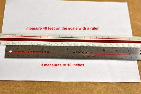
Quick Measure Tool

This tool allows you to quickly display measurments by moving your curser anywyere on the drawing. Just select the tool and it will display dimensions as you move. This will be an ideal way to check your work. Distances, dimensions and angles are all displayed as you move your mouse over and between objects.

Quick Measure Tool for AutoCAD 2020

New Dark Theme

This new theme is much easier on the eyes than the traditional black background theme. The dark theme now has a modern dark blue interface that will help fight fatigue and is more comfortable to view on your computer or phone.

AutoCAD 2020 new dark theme

Blocks Palette

This new feature makes choosing and finding blocks much easier. Includes visual galleries, so you no longer need the names memorized. This also helps organize your blocks by displaying recently used blocks, so you do not have to search every time.

AutoCAD 2020 on the Cloud

You can now work out of the cloud with partnerships with Microsoft and Box. Box (formerly known as Dropbox) and Microsoft with their OneDrive service can let you work from any location. This can also help you collaborate on projects. Back your projects up, so you don’t have to worry about failed hardware.

DWG Compare

Easily compare two versions of a drawing, without having to leave your current window. Now you have the ability to toggle on and off the comparison within the new DWG Compare toolbar.

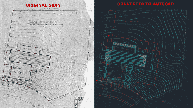
If you would like to learn more about the new features in AutoCAD 2020, check out the list of features on the AutoCAD website. At Convert2AutoCAD, we can take your drawings, and converted them to layered vector DWG files. Contact us for pricing and information.

Posted by Michael Mellor

AutoCAD Scale Factor Charts

AutoCAD Scale Factors Charts

Here are some simple charts to help you convert drawing scale to scale factor, for working in CAD

Convert your PDF to AutoCAD

Architectural Scales

Drawing
Scale
Scale
Factor
Viewport
Scale
Decimal
Scale
1/16″ = 1′-0″ 192 1/192xp .0625″ = 1′-0″
3/32″ = 1′-0″ 128 1/128xp .09375″ = 1′-0″
1/8″ = 1′-0″ 96 1/96xp .125″ = 1′-0″
3/16″ = 1′-0″ 64 1/64xp .1875″ = 1′-0″
1/4″ = 1′-0″ 48 1/48xp .25″ = 1′-0″
3/8″ = 1′-0″ 32 1/32xp .375″ = 1′-0″
1/2″ = 1′-0″ 24 1/24xp .50″ = 1′-0″
3/4″ = 1′-0″ 16 1/16xp .75″ = 1′-0″
1″ = 1′-0″ 12 1/12xp 1″ = 1′-0″
1 1/2″ = 1′-0″ 8 1/8xp 1.5″ = 1′-0″
3″ = 1′-0″ 4 1/4xp  3″ = 1′-0″

Engineering Scales

DRAWING SCALE SCALE FACTOR VIEWPORT SCALE
1″ = 10′-0″ 120 1/120xp
1″ = 20′-0″ 240 1/240xp
1″ = 30′-0″ 360 1/360xp
1″ = 40′-0″ 480 1/480xp
1″ = 50′-0″ 600 1/600xp
1″= 60′-0″ 720 1/720xp
1″ = 70′-0″ 840 1/840xp
1″ = 80′-0″ 960 1/960xp
1″ = 90′-0″ 1080 1/1080xp
1″ = 100′-0″ 1200 1/1200xp

We can convert your PDF files to fully layered AutoCAD DWG files.


Send us your PDF for a free quote.

PDF to CAD

Send over your PDF plan to have it converted to fully layered vector CAD file.
Posted by Michael Mellor in AutoCAD tips
Learn AutoCAD Online

You don’t need to go to a university to learn AutoCAD

Today we are going to discuss where to learn AutoCAD online. These are good if you want to give AutoCAD a try, or are an architect, engineer or drafter, that wants to move away from hand drawn plans, and move into digital CAD drafting. Some of these are free, some of them are subscription based. These are not accredited courses. Before starting, you need CAD software, and AutoCAD by Autodesk is the gold standard. You can download a free educational version of AutoCAD. You can also try some CAD alternatives.

Now lets get down to the list:

  • LinkedIn Learning $29.99 a month – LinkedIn Learning (formally Lynda.com) has lots of video courses and tutorials, for the beginner and novice alike. I have tried their courses, and their video format is easy to follow.
  • MyCadSite.com Free – This is a real cool set of lessons that include text, photos and videos. This is a fantastic resource for beginners and novice skill levels. You don’t need to sign up for an account, all the material is there for the public.
  • Tutorial45 Free – This is a great site for beginners. It includes a lot of step-by-step instructions with screenshots.
  • CadTutor Free – Some great video instruction, though the material is a little dated, I think most of the information is still very useful.
  • Skillshare $15.00 a month – Decent video courses geared towards beginners to help you learn AutoCAD.
  • CAD in Black Free – This is a YouTube channel consisting of many video tutorials on AutoCAD.

I hope this list helps you learn autocad online. I also hope it helps some of you get into AutoCAD, or expand your current knowledge of CAD. As always, if you need any files converted from PDF to CAD, send them to me for a free quote.

Posted by Michael Mellor
Alternative Programs to AutoCAD

I am often asked about alternatives to AutoCAD. The long running computer aided design program (CAD) AutoCAD has been the standard for 2D design for over 30 years. It was created by AutoDesk in 1982, and took the design world by storm. One issue people have with it, is it’s hefty price. With a yearly price tag of over $1,500 a year, it’s easy to see why people would be looking for a cheaper alternative.

Many people ask me if there is any alternatives to AutoCAD? The answer is yes, there is. If you have any suggestions, I would love to hear from you. Here’s a list of those programs below:

  • DraftSight – A free CAD program, with some features needing a paid license.
  • FreeCAD – A free open source 3D CAD design program.
  • SketchUp – Currently owned by Google, this program can help you work in 2D and 3D. It is free for non-commercial use.
  • BricsCAD – A professional design program, with paid licensing.
  • LibreCAD – Free, open sourced 2D CAD program.
  • SolidWorks – 3D CAD program with purchase tier options.
  • BRL-CAD – Free, open source modeling CAD.
  • SolveSpace – Free, open source 2D and 3D CAD for modeling parts.
  • NanoCAD – 2D and 3D design program that is fairly inexpensive.

We happen to use AutoCAD, and can help you with your design project. If you would like to have your PDF plans converted to AutoCAD DWG, submit them here for a free quote.

Posted by Michael Mellor

This also works if you want to convert imperial to metric

We often get requests to convert an architectural or engineering CAD drawing from metric to imperial measurements. Converting from metric to imperial in AutoCAD is easier than you might think. This may seem complicated, but it really isn’t. There are a few quick commands that makes it pain free. There are two methods to accomplish this.

Using the INSERT command:

  1. Create a new blank drawing using a template that is in the target units (for example acadiso.dwt for Metric or acad.dwt for Imperial).
  2. At the command line, enter INSERT.
  3. In the Insert dialog box, browse to the original DWG file.
  4. Check the box to Explode.
  5. Click OK and specify an insertion point.

PDF to CAD

Send over your PDF plan to have it converted to fully layered vector CAD file.

Using the SCALE command:

  1. At the command line, enter SCALE.
  2. At the Select objects prompt, enter All, then hit Enter.
  3. Enter 0,0 for the base point.
  4. When prompted for scale factor, enter the appropriate scale factor for the units to be converted, based on the following list:

Scale Factors:

Inches to Millimeters = 25.4
Millimeters to Inches = 0.0393701

Inches to Centimeters = 2.54
Centimeters to Inches = 0.393701

Feet to Millimeters = 304.8
Millimeters to Feet = 0.00328084

Feet to Centimeters = 30.48
Centimeters to Feet = 0.0328084

Note: For the SCALE command method, adjust the dimension text and arrowhead height in the dimension style as needed.

To have your plans professionally converted to AutoCAD, submit your files here for a fast quote.

Source: Autodesk.com

How to convert metric to imperial measurements in AutoCAD
Posted by Michael Mellor

We can work in metric! Today we had a call from a gentleman in Australia who said our website does not mention metric. We can convert in metric or imperial measurements, and it is no extra charge! We are in the USA, but we really love metric. If you would like to have a plan converted to a layered AutoCAD file, send over an image of any file type, and we will respond quickly with a quote.

If you would like to convert metric to imperial, or imperial to metric, check out our handy conversion chart. For a metric to imperial online calculator check out this one from metric-conversions.org.

We work in imperial or metric measurements
We can convert your plan in metric or imperial measurements.
Posted by Michael Mellor
Revit Hotkey and Shortcuts Chart

Shortcut Commands by Category

Here is a list of commands, hotkeys and keyboard shortcuts for the Autodesk 3D design program Revit. If you would like to learn more about Revit and AutoCAD services, contact us.

Annotate

DIALIGNED DIMENSION / Creates an aligned dimension.
DLDETAIL LINE / Creates view-specific lines.
ELSPOT ELEVATION / Displays the elevation of a selected point.
FRFIND/REPLACE / Find and replace.
GPMODEL GROUP:CREATE GROUP; DETAIL GROUP:CREATE GROUP / Creates a group of elements.
RTTAG ROOM; ROOM TAG / Tags the selected room.
TGTAG BY CATEGORY / Applies tags to elements based on their categories.
TXTEXT / Adds text.

Analyze

AAADJUST ANALYTICAL MODEL / Adjusts the analytical model of the structural member in relation to those of the elements to which it joins.
DCCHECK DUCT SYSTEMS / Examines the mechanical systems in a project to verify that each system is assigned to a userdefined system, and properly connected.
ECCHECK CIRCUITS / Verifies all circuits for proper connections to panels and valid system assignments.
LDLOADS / Applies point, line and area loads to a model.
LOHEATING AND COOLING LOADS / Prepares a heating and cooling load analysis report based on an existing building model.
PCCHECK PIPE SYSTEMS / Examines the piping systems in a project to verify that each system is assigned to a user-defined system, and properly connected.
PSPANEL SCHEDULES / Generates a panel schedule for a specific panel.
RARESET ANALYTICAL MODEL / Restores the analytical model alignment methods to auto-detect.

Architecture

CLCOLUMN; STRUCTURAL COLUMN / Adds a vertical load-bearing element to the building model.
CMPLACE A COMPONENT / Place a component.
DRDOOR / Adds a door to the building model.
GRGRID / Places column grid lines in the building design.
LLLEVEL / Places a level in view.
RMROOM / Creates a room bounded by model elements and separation lines.
RPREFERENCE PLANE / Creates a reference plane using drawing tools.
RTTAG ROOM; ROOM TAG / Tags the selected room.
SBFLOOR:FLOOR: STRUCTURAL / Adds structural floors to a building model.
WAWALL; WALL:WALL: ARCHITECTURAL / Creates a non-bearing wall or a structural wall in the building model.
WNWINDOW / Places a window in a wall or skylight in a roof.

Collaborate

EREDITING REQUESTS / Displays a list of usersí requests to borrow elements in worksets, as well as pending requests.
RL or RWRELOAD LATEST / Loads the latest version of the central model.

Context Menu

MPMOVE TO PROJECT / Move the model relative to a shared coordinate system.
R3DEFINE A NEW CENTER OF ROTATION / Relocates center of rotation when rotating elements.
RARESTORE ALL EXCLUDED / Restores all excluded parts and elements.
RBRESTORE EXCLUDED MEMBER / Restores an excluded member.
RCREPEAT LAST COMMAND / Repeats the last command.
SASELECT ALL INSTANCES: IN ENTIRE PROJECT / Selects all of the elements that are similar to the selected element in the current view, or throughout the project.

Contextual Tabs

//DIVIDE SURFACE / Applies a division grid along a surface in a conceptual design.
AAADJUST ANALYTICAL MODEL / Adjusts the analytical model of the structural member in relation to those of the elements to which it joins.
ADATTACH DETAIL GROUP / Creates an attached detail group.
APADD TO GROUP / Adds elements to a group.
BSSTRUCTURAL BEAM SYSTEM; AUTOMATIC BEAM SYSTEM / Creates a layout that is used to control the number and spacing of a series of parallel beams.
CGCANCEL / Cancels an action.
DIALIGNED DIMENSION / Creates an aligned dimension.
EGEDIT GROUP / Edits a group.
ELSPOT ELEVATION / Displays the elevation of a selected point.
EPEDIT PAR / Edits a part element.
EUUNHIDE ELEMENT / Enables a hidden element to appear in view.
EWEDIT WITNESS LINES / Edits a witness line.
FGFINISH / Finishes editing a group.
HTSHOW HELP TOOLTIP / Displays the Help Tooltip.
JPJUSTIFICATION POINTS / Sets a justification point for relocating elements.
JYZOFFSET / Offsets an element in the z direction.
JZSHOW HELP TOOLTIP / Displays the Help Tooltip.
LIMODEL LINE; BOUNDARY LINE; REBAR LINE / Places a new line.
PP or CTRL-1 or VPPROPERTIES; TOGGLE PROPERTIES PALETTE / Toggles the Properties palette.
RARESTORE ALL EXCLUDED / Restores all excluded parts and elements.
RGREMOVE FROM GROUP / Removes elements from a group.
RHTOGGLE REVEAL HIDDEN ELEMENTS MODE / Toggles the Reveal Hidden Elements Mode.
RPREFERENCE PLANE / Creates a reference plane using drawing tools.
UGUNGROUP / Ungroups members of a group.
VUUNHIDE CATEGORY / Enables a hidden category to appear in view.

Create

CMPLACE A COMPONENT / Place a component.
DALIGNED DIMENSION / Creates an aligned dimension.
FRFIND/REPLACE / Find and replace.
GPMODEL GROUP:CREATE GROUP; DETAIL GROUP:CREATE GROUP / Creates a group of elements.
LIMODEL LINE; BOUNDARY LINE; REBAR LINE / Places a new line.
LLLEVEL / Places a level in view.
MDMODIFY / Enters selection mode to select elements to modify.
PP or CTRL-1 or VPPROPERTIES; TOGGLE PROPERTIES PALETTE / Toggles the Properties palette.
RPREFERENCE PLANE / Creates a reference plane using drawing tools.
TXTEXT / Adds text

Manage

ESMEP SETTINGS:ELECTRICAL SETTINGS / Accesses dialog box to specify wiring parameters, voltages definitions, distribution systems, cable tray and conduit settings, and load calculation and circuit numbering settings.
MSMEP SETTINGS:MECHANICAL SETTINGS / Accesses dialog box to configure component sizes, and the behavior and appearance of the mechanical systems.
SUADDITIONAL SETTINGS:SUN SETTINGS / Opens the sun settings dialog box.
UNPROJECT UNITS / Opens the Project Units tool.

Modify

ALALIGN / Aligns one or more elements with selected element.
ARARRAY / Creates a linear or radial array of selected elements.
CO or CCCOPY / Copies selected element(s).
CPCOPE; APPLY COPING / Applies coping to steel beam or columns.
CSCREATE SIMILAR / Creates an element of the same type as the selected element.
DEDELETE / Removes selected element(s) from the building model.
DIALIGNED DIMENSION / Creates an aligned dimension.
DMMIRROR – DRAW AXIS / Reverses the position of a selected model element, using a user-generated line as the mirror axis.
EHHIDE IN VIEW:HIDE ELEMENTS / Hides an element from view.
ELSPOT ELEVATION / Displays the elevation of a selected point.
EODOVERRIDE GRAPHICS IN VIEW:OVERRIDE BY ELEMENT / Changes the graphic display settings for selected elements in the current view.
LIMODEL LINE; BOUNDARY LINE; REBAR LINE / Places a new line.
LWLINEWORK / Overrides the line style of selected line in the active view only.
MAMATCH TYPE PROPERTIES / Opens the Match Type tool to convert one or more elements to match the type assigned to another element.
MMMIRROR – PICK AXIS / Reverses the position of a selected model element, using a selected line as the mirror axis.
MVMOVE / Moves a selected element.
OFOFFSET / Moves a selected model line, detail line, wall, or beam a specified distance perpendicular to its length.
PNPIN / Locks a model element in place.
PP or CTRL-1 or VPPROPERTIES; TOGGLE PROPERTIES PALETTE / Toggles the Properties palette.
PTPAINT / Opens the Paint tool.
RCCOPE:REMOVE COPING / Removes coping.
RESCALE / Resizes the selected element.
ROROTATE / Rotates selected element around an axis.
RPREFERENCE PLANE / Creates a reference plane using drawing tools.
SFSPLIT FACE / Divides the face of an element into regions for application of different materials.
SLSPLIT ELEMENT / Cuts an element (such as a wall or line) at a selected point.
TRTRIM/EXTEND TO CORNER / Trims or extend one or more elements to form a corner.
UPUNPIN / Unpins an element that is locked in position or an element that is driven by its host system.
VHHIDE IN VIEW:HIDE CATEGORY / Hides an element category from view.

Navigation Bar

322D MODE / Navigates the view using only 2D navigation options.
3FFLY MODE / Simulates flying through a model.
3OOBJECT MODE / Navigates and reorients the view in the direction of the controller cap.
3WWALK MODE / Simulates walking through a model.
ZAZOOM ALL TO FIT / Zooms to fit all in view.
ZE or ZF or ZXZOOM TO FIT / Zooms to fit.
ZO or ZVZOOM OUT(2X) / Zooms out the project view by 2X.
ZP or ZCPREVIOUS PAN/ZOOM / Returns to previous pan or zoom.l
ZR or ZZZOOM IN REGION / Zooms to a region.
ZSZOOM SHEET SIZE / Zooms to sheet size.

Snaps

PCSNAP TO POINT CLOUDS / Snaps to point cloud.
SCCENTERS / Snaps to center
SEENDPOINTS / Snaps to endpoints.
SIINTERSECTIONS / Snaps to intersection.
SMMIDPOINTS / Snaps to midpoint.
SNNEAREST / Snaps to nearest.
SOSNAPS OFF / Turns snaps off.
SPPERPENDICULAR / Snaps to perpendicular.
SQQUADRANTS / Snaps to quadrant.
SRSNAP TO REMOTE OBJECTS / Snaps to objects that are not near the element.
SSTURN OVERRIDE OFF / Turns off override feature.
STTANGENTS / Snaps to tangent.
SWWORK PLANE GRID / Snaps to the work plane grid.
SXPOINTS / Snaps to points.

Structure

BMSTRUCTURAL FRAMING: BEAM / Adds a load-bearing structural beam element to the building model.
BRSTRUCTURAL FRAMING: BRACE / Adds diagonal members that are connected to beams and columns.
BSSTRUCTURAL BEAM SYSTEM; AUTOMATIC BEAM SYSTEM / Creates a layout that is used to control the number and spacing of a series of parallel beams.
CLCOLUMN; STRUCTURAL COLUMN / Adds a vertical load-bearing element to the building model.
CMPLACE A COMPONENT / Place a component.
FTSTRUCTURAL FOUNDATION: WALL / Creates a wall foundation for the building model.
GRGRID / Places column grid lines in the building design.
LLLEVEL / Places a level in view.
RNREINFORCEMENT NUMBERS / Defines or edits numbering sequences by partition for rebar and fabric sheets.
RPREFERENCE PLANE / Creates a reference plane using drawing tools.
SBFLOOR:FLOOR: STRUCTURAL / Adds structural floors to a building model.
WAWALL; WALL:WALL: ARCHITECTURAL / Creates a non-bearing wall or a structural wall in the building model.

System

ATAIR TERMINAL / Places a register, grille or diffuser.
CMPLACE A COMPONENT / Place a component.
CNCONDUIT / Draws a rigid conduit run.
CTCABLE TRAY / Draws a cable tray run.
CVCONVERT TO FLEX DUCT / Converts a section of rigid duct to flexible duct.
DADUCT ACCESSORY / Adds duct accessories, such as dampers, in duct systems.
DFDUCT FITTING / Places duct fittings (elbows, tees, end caps, and so on) in duct systems.
DTDUCT / Draws ductwork in the building model.
EEELECTRICAL EQUIPMENT / Places electrical equipment, such as panels and switch gear.
EWARC WIRE / Draws an arced wire run.
FDFLEX DUCT / Draws flexible ductwork in the building model.
FPFLEX PIPE / Draws flexible pipes.
LFLIGHTING FIXTURE / Adds a lighting fixture element.
MEMECHANICAL EQUIPMENT / Places mechanical equipment such as boilers, furnaces or fans.
NFCONDUIT FITTING / Places conduit fittings.
PAPIPE ACCESSORY / Adds pipe accessories.
PFPIPE FITTING / Draws a pipe fitting in a piping system.
PIPIPE / Draws rigid piping.
PXPLUMBING FIXTURE / Places a plumbing fixture.
RPREFERENCE PLANE / Creates a reference plane using drawing tools.
SKSPRINKLER / Places a sprinkler
TFCABLE TRAY FITTING / Places cable tray fittings.

View

FN9SYSTEM BROWSER / Finds components that are not assigned to a system.
KSKEYBOARD SHORTCUTS / Assigns key sequences to tools.
PP or CTRL-1 or VPPROPERTIES; TOGGLE PROPERTIES PALETTE / Toggles the Properties palette.
RDRENDER IN CLOUD / Renders 3D views online.
RGRENDER GALLERY / Enables access to multiple versions of renderings, render images as panoramas, change rendering quality, and apply background environments to rendered scenes.
RRRENDER / Creates a photorealistic image of the building model.
TLTHIN LINES / Displays all lines on the screen as a single width, regardless of zoom level.
VG or VVVISIBILITY/GRAPHICS / Controls the visibility and graphic display of model elements, datum elements, and viewspecific elements for each view in a project.
WCCASCADE WINDOWS / Arranges all open windows in a series in the drawing area.
WTTILE WINDOWS / See all open views at the same time.

View Control Bar

CXTOGGLE REVEAL CONSTRAINTS MODE / Toggles the constraints in a view.
GDGRAPHIC DISPLAY OPTIONS / Opens the Graphics dialog box.
HCHIDE CATEGORY / Hides all selected categories in the view.
HHHIDE ELEMENT / Hides an element from view.
HIISOLATE ELEMENT / Isolates selected elements.
HLHIDDEN LINE / Displays the image with all edges and lines drawn except those obstructed by surfaces.
HRRESET TEMPORARY HIDE/ISOLATE / Restores any temporarily hidden elements or categories.
ICISOLATE CATEGORY / Isolates selected categories.
RDRENDER IN CLOUD / Renders 3D views online.
RGRENDER GALLERY / Enables access to multiple versions of renderings, render images as panoramas, change rendering quality, and apply background environments to rendered scenes.
RHTOGGLE REVEAL HIDDEN ELEMENTS MODE / Toggles the Reveal Hidden Elements Mode.
RRRENDER / Creates a photorealistic image of the building model.
RYRAY TRACE / Opens Ray Trace visual style, enabling a photorealistic rendering mode that allows panning and zooming around the model.
SDSHADED WITH EDGES / Applies a shaded edge.
WFWIREFRAME / Displays the image of the model with all edges and lines drawn, but with no surfaces drawn.
Posted by Michael Mellor
American Architects Listings at the AIA

A listing of all architects in the AIA (American Institute of Architects)

Finding an architect in your area just got easier. The AIA has a complete searchable listing of all of its members by name, zip code, city, state, and building type. This makes it easy to find any architect in the United States.

About the American Institute of Architects

The American Institute of Architects has been around for over 150 years and has over 90,000 members, making it the largest architect organization in the United States. We are proud supporters by sponsoring events from local chapters AIA Palomar, and San Diego. To read more about the structure and history, check out the their Wikipedia page.

About Convert2AutoCAD

We convert paper or PDF plans to fully layered AutoCAD DWG files. For a free quote send over your files. Convert2AutoCAD is part of the Del Mar Blue family. We are a small business located in California.

AIA The American Institute of Architects logo

Posted by Michael Mellor

I have a sheet that is not to scale, but I want it to scale

You can learn to scale an architectural plan to any scale you want

Many times, we receive plans from customers that are reduced to a page size, or are to a scale that they can’t use. For example, they have a printout of a plan that is on a small sheet, say size 8.5×11 inches. Well, they want that same page enlarged to the full scale that it was originally. In this example we are enlarging a sheet that we don’t know the scale, to 1 inch = 4 feet, otherwise known as 1/4 scale. This sample works only as long as the proportions are in tact. If the image has been stretched in any direction, this method will not work and you will have to edit it in image editing software like Adobe Photoshop to get all dimensions to scale. Since I am in the U.S., I will be showing you this procedure using imperial measurements.

Here are the things that you will need.

  1. An architectural scale
  2. A regular inches ruler
  3. Scratch paper
  4. A calculator
Supplies needed to scale your plans
Supplies you will need to enlarge and reduce your plans to scale.

We need the sheet that you are printing from to be printed out. Be sure that when you print it, to select “Actual Size” and not “Fit.” This will ensure the sheet you are measuring does not change when you print it.

The formula we use for this is simple.

WANT ÷ IS x 100 = percentage

WANT = size you want that dimension to measure

IS = the size that dimension currently measures to

PERCENTAGE = the percentage  to enlarge or reduce the image

Find a large dimension on the sheet that is a full number in feet. Try to avoid a dimension like 12’9”. In my case, I have found a dimension that shows 40-feet.

measure dimension with ruler
Measure your original sheet that you are trying to enlarge


PDF to CAD

Send over your PDF plan to have it converted to fully layered vector CAD file.

Finding the IS

Take a measurement of that dimension using your ruler and write it down. In my case, that 40-feet measures to 3 ⅞ inches. It helps if you convert the fraction to decimal. Using your calculator, divide 7 by 8 and you come up with 0.875. So the length is 3.875 inches.

Finding the WANT

Take your architectural scale and find the 1/4 side and measure up to the 40 notch. This is how long we want that dimension to be. Now measure that to see how long that is in inches. Use your ruler, and hold it up to your scale, like you can see in the photo. In my case, it measures to exactly 10-inches.

Measure your desired dimension on the architectural scale, with a ruler
Measure your desired dimension on with a ruler

Now we just have to do the math

10 inches (WANT) divided by 3.875 (IS) multiplied by 100 gives us 258.06%. This formula will get you very close, but you will want to print the sheet enlarged to that percentage and measure it with your architectural scale, and adjust up or down a percentage or two.

"Measure
Take a measurement to see if you need to enlarge or reduce a bit to get it exact.

I have also made a chart so you can find the enlargement or reduction percentage to change the scale of a plan. Here is a scale factor chart, that might help you. Check out this link from Autodesk about resizing AutoCAD plans. I hope this helps you enlarge and reduce architectural drawings. If you have any questions, please contact us. If you would like any sheets converted to AutoCAD, send it over for a quick quote.

Posted by Michael Mellor
Del Mar Blue Print celebrates 40 years!

A milestone

I am happy to be a part of the Del Mar Blue Print family! Even though I’ve only been there for a bit over a quarter of it’s 40 year history, I feel like I’ve been here for the whole time. Convert2AutoCAD has been here for around 2 years, and could not happen without the great support from Mike Kraus and the Del Mar Blue team. From a single person shop, to having over 20 employees and printing and shipping worldwide. Del Mar Blue Print has constantly been on the cutting edge of technology, while keeping it’s small family feel. Read a short history of the company at the Del Mar Blue Print blog.

Posted by Michael Mellor
Defending Brutalist Architecture

What is brutalist architecture?

I found a very informative podcast about a form of architecture that does not get much praise. Brutalist architecture came out of the 1960’s Europe, when it was too expensive to build from steel. It mostly traces back to French-Swiss architect Le Corbusier, and is known for it’s use of raw concrete. Many people think of brutalism as “ugly” and “communist looking”, but there are many examples of amazing structures in this style, including the Geisel Library in my home town of San Diego.

Brutalist architecture Geisel Library

Geisel Library at University of California at San Diego is an example of brutalist architecture


While it’s true, sometimes it’s used in boring ways, I think you would agree that the above building is hardly boring. This topic is explored in more detail at the WBUR show “Here and Now” in both podcast, and written form.


Brutalist architecture Qualcomm / Jack Murphy Stadium in San Diego

Qualcomm / Jack Murphy Stadium in San Diego

Another example in San Diego is Jack Murphy / Qualcomm Stadium in San Diego, completed in 1967. More about that stadium can be found in this Voice of San Diego article. The stadium has most recently hosted the San Diego Chargers football team, and used to host the San Diego Padres, before Petco Park was built.

Brutalism architecture arches

Brutalism architecture arches

Posted by Michael Mellor
PDF2CAD vs. Convert2AutoCAD [video]

Can PDF2CAD do what we do?

The short answer is, not even close!

Many of our customers think that our PDF to DWG service is done with software. I decided to find a software that claims to do this, and tried it with the program PDF2CAD. This program is free for 30 days, and then you must pay $100. What this software does offer is a conversion of your PDF to a single layered DWG file, that looks exactly like your PDF. There are no lines, it’s only dots that are not easy to manipulate like vector lines. How is this program useful? It could be of use if you have a PDF that you just want to draw over, but it is not useful for manipulation.

“Use pdf2cad to transform vector PDF files into editable CAD drawings such as DXF and DWG saving hours of redraw time.”

This quite is taken from their website. This is only true if  you start with a multi-layered PDF. But if you have one of those, you can just import it into CAD and have the layers anyway. We can take a raw scanned PDF or TIF and convert it to DWG with layers, colors, layer names, and readable fonts. Everything is vector.

What makes Convert2AutoCAD better?

We redraw your plan by hand in AutoCAD by expert drafters. This is lets you manipulate each line and hatch, and your plans will look very clean. This is also useful for old plans that are difficult to read. They will look like brand new plans. Check out the video below to see both PDF2CAD and Convert2CAD converting the same scanned plan. Get a quote on conversions to CAD. Also our pricing is always on our website, so there will be no unexpected bills.

The video above compares PDF2CAD to Convert2AutoCAD.

Posted by Michael Mellor
5 Ways to Grow Your Business

5 Ways to Grow Your Business

There are so many fun things to do in the summer. We all want to have fun, but grow our business at the same time. Here are some things you can do to improve business this summer.

  1. Reinforce your brand with signage. We can help you with signs at your job sites, and offices. Your business will benefit from custom signs. We print our signs in-house and can help you with design. We can print on a variety of materials such as foamcore, gator board, coroplast, and even plexiglass acrylic. Check out the options here.
  2. Send direct mail. I know, you’re reading a piece of digital marketing, and not a mailer, but let’s not dismiss the effectiveness of direct mail marketing! Direct mail marketing tends to be more trusted, and is more likely to be viewed. We can help you with your mailers and even add all the mailing addresses. You can read more about direct mail vs. digital marketing here.
  3. Business cards are still essential. They are not going away. I always keep at least 10 business cards in my wallet. We can set you up with a design, and print business cards for you. Here are some statistics on business cards designs. Also, be sure to get out to as many networking functions as you can.
  4. AutoCAD conversions. This is one of our fastest growing services. We can take your old plans, and give you a fully layered AutoCAD file. This is a game changer for architectural, engineering, construction, and any other design firms. This saves you so much time, and can be done in as short as next business day. We even offer discounts for bulk orders. Send over a file, and we can get you a quote right away.
  5. Vehicle and window graphics. Increase your visibility. We can add your logo, slogan, and contact information to your vehicle. At Del Mar Blue, we have a digital vinyl cutter, and can add lettering and logos to vehicles, glass, and smooth walls. We have done it on our vehicles and the windows of our headquarters. Check out some examples we’ve done here.
Posted by Michael Mellor
How this service can make you money

Don’t you wish you could take on more jobs, while doing less work?

Well you can! Literally, you can have jobs done while you sleep, making you more money!

Much of the architects job consists of redrawing plans, for remodels. For years, the procedure was to get old plans from the city or county, have them scanned at our local reprographics shop, import them into AutoCAD, and redraw over the lines. This was a tedious, costly, and time consuming process, that is now totally avoidable. Architects charge between $75 and $150 per hour. This makes it very expensive to redraw plans, that could take many hours. Imagine sending off PDF plans, and having them available the following day. This service can make you money!

We supply you with layered files

We know importing a PDF into AutoCAD is easy. This service goes much more beyond that. We will give you a fully layered DWG file, using industry standards in pen weight, layer name, and layer colors. Each drawing is done with precise accuracy. You can start working right away.

Even ugly old plans?

This service can also be used for ugly, presentable paper plans that are hard to read, and unpleasant to touch. This includes old blueprints, sepia, mylar, and vellum plans. We have the capability to scan sheets up to 36 inches wide. You will be given a file that is clear to read, and very presentable. Take old hand drawn plans, and have them turned into modern AutoCAD files. If you would like for us to scan your plans, contact us and we will make it happen.

How long have you offered this service?

We have been offering this conversion to AutoCAD service for over 15 years. We have hundreds of happy customers including architects, engineers, plumbers, landscape, interior designers, machinists, electricians, counties, cities, water districts and drafters.

How do we do it?

We take your scan, and redraw it in AutoCAD by our expert drafters. This is a manual process, and is not automated with software. There is an actual human, redrawing your plans! This ensures accuracy and quality.

What does it cost?

We are pretty straight forward with our pricing. We charge by the sheet size. You can find our pricing here.

I have files that I want converted. How do I get them to you?

You can send the files with through or online order form. We will get right back to you with a quote, and estimated time of completion. If you have any questions, you can always reach us by calling (858)755-5134


Posted by Michael Mellor
Converted tattered old site plan to AutoCAD

This old blueprint was converted to a AutoCAD DWG file

This service is a difference maker

We had a customer come to us with a very old, tattered blueprint that he wanted to have converted to AutoCAD. This happens a lot, and many times, the customer is unsure if it can even be done., well, it can be done! I took the old plan, and scanned it on our black and white scanner, and had one of our expert drafters redraw it in AutoCAD to a DWG file. As you can see in the image above, the plan on the left is the original scan of the blueprint. The image on the right is the resulting AutoCAD file. The customer was very pleased with the result, and was able to start his design project right away.

Fast

This service is normally a 3-business day turnaround. We also offer 24-hour turnaround for only an extra $30 per sheet. You will not be able to hire a drafter for less than our prices. Our service is fast, and accurate. We guarantee our work, if the result is not what you expected, we will make the changes for free. We do more than residential, we also do commercial, retail, government, medical, municipal, utility, golf courses, hotels, parks, roads and bridges.

Money and time saved

Our customer was very happy with the result. He was able to start the remodel design on the home, and sent the AutoCAD file to his landscape architect to begin designing the new landscape. Using the topography lines, he was able to add in trees, a deck, and retaining walls. Instead of redrawing plans, you can send the work to us, giving you more time to design. If you would like to use this service, contact us today. We can answer your questions, and get you a fast quote.

Posted by Michael Mellor
Most used AutoCAD keyboard shortcuts

Most used AutoCAD keyboard shortcuts

Here are the most commonly used AutoCAD 2018 keyboard shortcuts.

Get more work done!

Keyboard shortcuts help you do navigate AutoCAD much quicker than clicking with the mouse. Get to know these commands to speed up your productivity. Print up this chart of keyboard shortcuts for AutoCAD 2018. We can save you more time by converting PDF plans to DWG AutoCAD files. From there, you can simply edit in AutoCAD. Contact us for a free quote.

PDF to CAD

Send over your PDF plan to have it converted to fully layered vector CAD file.
KeypressCommandDescription
F1HELPCalls for Help screen
F2TEXTSCRToggles the Text screen display
F3OSNAPToggles Object Snap mode
F43DOSNAPToggles 3D Object Snap mode
F5ISOPLANEToggles Isoplane mode
F63DOSNAPToggles 3D Snap to Plane mode
F7GRIDMODEToggles Grid mode
F8ORTHOToggles Ortho mode
F9SNAPToggles Snap mode
F10POLARToggles Polar mode
F11OTRACKToggles Object Track mode
F12DYNMODEToggles Dynamic Input mode
Ctrl+SaveQSAVESaves the drawing
Ctrl+OpenOPENDisplays the Select File dialog box
Ctrl+PPLOTDisplays the Plot dialog box
Ctrl+Tab Switches to the next open drawing
Ctrl+PgUp Switches to the next tab in the current drawing
Ctrl+PgDn Switches to the previous tab in the current drawing

For more shortcuts, visit the AutoCAD website.

Posted by Michael Mellor
Convert Imperial Inches to Metric Centimeters Chart

Convert Imperial Inches to Metric Centimeters Chart

Work with imperial and metric units with ease

Many architects and engineers have the need to work between imperial and metric measurements, so here is a quick and easy conversion chart to reference at any time, for your building and designing needs.

Us this easy chart to convert your inches to centimeters, or centimeters to inches. If you have plans that you would like converted to AutoCAD, send them to us for a quick quote.

Inches (“) to Centimeters (cm) conversion chart

0.01 in 0.0254000 cm
1/64 in 0.0396875 cm
1/32 in 0.0793750 cm
1/16 in 0.15875 cm
0.1 in 0.2540 cm
1/8 in 0.3175 cm
1/4 in 0.635 cm
1/2 in 1.27 cm
1 in 2.54 cm
2 in 5.08 cm
3 in 7.62 cm
4 in 10.16 cm
5 in 12.70 cm
6 in 15.24 cm
7 in 17.78 cm
8 in 20.32 cm
9 in 22.86 cm
10 in 25.40 cm
20 in 50.80 cm
30 in 76.20 cm
40 in 101.60 cm
50 in 127.00 cm
60 in 152.40 cm
70 in 177.80 cm
80 in 203.20 cm
90 in 228.60 cm
100 in 254.00 cm

Centimeters (cm) to Inches (“)

(decimal) Inches (“)  (fraction)
0.01 cm 0.0039 in 0 in
0.1 cm 0.0394 in 3/64 in
1 cm 0.3937 in 25/64 in
2 cm 0.7874 in 25/32 in
3 cm 1.1811 in 1 3/16 in
4 cm 1.5748 in 1 37/64 in
5 cm 1.9685 in 1 31/32 in
6 cm 2.3622 in 2 23/64 in
7 cm 2.7559 in 2 3/4 in
8 cm 3.1496 in 3 5/32 in
9 cm 3.5433 in 3 35/64 in
10 cm 3.9370 in 3 15/16 in
20 cm 7.8740 in 7 7/8 in
30 cm 11.8110 in 11 13/16 in
40 cm 15.7840 in 15 3/4 in
50 cm 19.6850 in 19 11/16 in
60 cm 23.6220 in 23 5/8 in
70 cm 27.5591 in 27 9/16 in
80 cm 31.4961 in 31 1/2 in
90 cm 35.4331 in 35 7/16 in
100 cm 39.3701 in 39 3/8 in

You can also find a conversion calculator at RapidTables.com

Posted by Michael Mellor

From hard to read, to blueprint scans, to clear, legible AutoCAD files

Here is an actual conversion we did for a customer. As you can see, the original scan is a hard to read floor plan, with lots of noise, and dark spots. This is common when scanning old blueprints. Our customer is doing a remodel on the house, and instead of redrawing the whole house from scratch, they saved a lot of time by having us convert their PDF to an AutoCAD DWG file. Now they can make changes to the walls, doors, windows, and fixtures. This service is also good for elevations, electrical, mechanical, plumbing, structural, and landscape plans. You can then work on it with AutoDesk AutoCAD, or any other CAD program that accepts DWG files.

Here’s the scanned blueprint floor plan

Original PDF scan that we used to convert to PDF

Original PDF scanned floor plan that we used to convert to PDF (click to enlarge)

As you can see, the scan is difficult to read, many lines are light, and there are a lot of blurry text. We took the scan, and redrew it in CAD.

Here is the AutoCAD DWG file

DWG AutoCAD file we were able to return to the customer so he could begin the remodel.

DWG AutoCAD file we were able to return to the customer so he could begin the remodel. (click to enlarge)

Layered

As you can see, this is a drastic difference. Our customer was given a professional, vector image, that is broken down into layers as  you can see in the image below:

Colored PDF with layers

Colored PDF with layers (click to enlarge)

The customer was extremely happy with the final product. The conversion took 24-hours, and the cost was less than $200. The customer is an architect, and said that “this would have taken me much longer, and cost me a lot more money.” We are happy to help out the construction industry take on more work. If you are interested in using this service for your construction or printing/reprographics company contact us.

For printing and document services, check out Del Mar Blue.

Posted by Michael Mellor
How Converting to AutoCAD Can Save You Money

Who doesn’t want to save money?

As they say, “a dollar saved, is a better than a dollar earned.”  This is very true for converting your files to AutoCAD. Here’s the ways using this service can save you money.

We know you are in this business to make money. Hiring a drafter is expensive, and you often have better things to do than to redraw old plans for a remodel or addition. Here’s a few reasons why this service not only can save you money, but can make you money.

  • Drawing one page from scratch can take 4 to 24 hours, that can cost you a lot of money.
  • Average hourly rate of an architect is $35 to $75 per hour.
  • We provide fully layered AutoCAD DWG files, that you can begin your remodel design right away.
  • This can be used for architectural, structural, engineering, plumbing, mechanical, shop drawings, as-built, calculations, details, kitchen, landscape, topographic, elevations, floor plans, sections, and any other type of plans you may have. We work in both imperial, and metric measurements.
  • We can also work with you to make design changes to plans, and a rate of only $30 per hour.
  • You can concentrate on design and business development, instead of redrawing plans.
  • Reprographics companies can offer this to their customers with a special rate.
  • Take on more jobs by having us handle a lot of the drafting.

As you can see, this service can help your company by giving you a jump start on your design and remodel projects. This service has helped out hundreds of our customers. Have the advantage over your competition. We can convert PDF, PLT, TIF, JPG, GIF, and even paper plans to fully layered AutoCAD DWG files. If you would like a free quote, Email us now.

Convert2AutoCAD is a small business residing in Del Mar, California. If you have any questions, please contact us.

Posted by Michael Mellor
Load more