AutoCAD 2021 features cloud storage, quick measure, drawing history, and more.
AutoCAD 2021 is here and has some robust new features. First released in 1982 by AutoDesk, it has remained the industry standard for architecture, engineering, and design. There are new features in 2021 that you should be aware of. We think you will be excited about many of of these updates. Here we will go over those.
New mobile and web apps. Now you can work from anywhere, on almost any device with new AutoCAD 2021 mobile and web apps.
Photo from Autodesk.com
Cloud storage connectivity. Seamlessly work from anywhere, because now your DWG files will be store remotely on the cloud. This is similar to Adobe’s Creative Cloud.
Photo from Autodesk.com
Version history. Now you can compare changes, throughout the life of a drawing.
Photo from Autodesk.com
Improved graphical performance. This update speeds up rendering and viewing of 2D and 3D graphics on your Windows and Macintosh computers. AutoCAD 2021 now takes full advantage of multi-core processors.
Photo from Autodesk.com
Blocks Palette. Now you can access your blocks from AutoCAD, or over the web. This feature also
Photo from Autodesk.com
There are many more features, but we are most excited about these. Some other new features include save to web and mobile, purge redesign, and Xref compare. For a full list of new features in AutoCAD 2021, check out this link. AutoCAD 2021 cost $1,690.00 for 1 year.
Autodesk also offers their 3D design software called Revit. Revit is a 3D BIM (Building Information Modeling) software that is slowly eclipsing AutoCAD as the leading design software.
Work from home, they are telling us. These are times unlike any that we have seen in recent memory. There is a global pandemic, that has forced the world economy to come to a screeching halt. The COVID-19 pandemic has changed all of our lives. Stay at home orders, social distancing rules, face-covering requirements and business closures. Many are not working, and many are working from home. If you are a designer, it may no longer be difficult to work from home.
Have a Remodel? We Can Help
Converting architectural, engineering, mechanical, plumbing, electrical, and landscape plans to CAD.
PDF to CAD
Send over your PDF plan to have it converted to fully layered vector CAD file.
Many times, we have clients who want changes to their existing home or business. An addition, second floor, updated electrical, more water efficient landscape. You could go to the site, take measurements, redraw the building in CAD, and make your changes from there. You could also get the original plans from the client, or local building department, and have the plans scanned, and sent to us to give you a fully layered CAD file. That way you can make your changes directly to the original plans. We can have the the plans back to you in as little as 24 hours.
Skilled CAD Drafters
Our team of highly skilled drafters can complete your drawing quickly and accurately.
Our team of over 100 skilled 2D and 3D designers are efficient and accurate. Delivering sharp, accurate design, for you to present to homeowners, builders or subcontractors. The Convert2AutoCAD team uses the best practices for layer names and colors.
Serving More Than Just Architects
We serve more than just architects.
Architects make up the majority of our customers, but we also serve many other industries. Some examples are health care, fabrication, engineering, construction, education, public works, government, defense, biotech, craft beer and wine, fashion, and tech. We are located in the United States, but we serve clients worldwide.
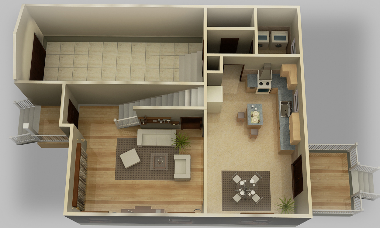
Architects are constantly wanting to help their customers visualize their new residence or remodel. This makes 3-D renderings more valuable than ever. They can leave nothing to the imagination of your customer, and show them spaces, materials, furniture, fixtures, windows and doors. In our example here, you can see hardwood floors, tile, stairs, curtains, sink, chairs, couches, stove, and a washer and dryer.
Affordable 3-D visualization
Prices start at $400, our 3-D architectural rendering services fit in any budget. This is the best possible way to show your vision, to your customers. We also offer 3-D elevation renderings, and even 3D video walk-through. Want an exact price and estimated time of completion? Send your files for a complete free estimate.
How is it done?
We work with a team of experienced drafters, using programs like Revit to model your design. This gives you a scale digital model using vector graphics, for limitless enlargement. We can also render images for you to use for print and web display. You will receive a JPG file that you can email to your customer.
We also offer 3-D printed buildings for your architectural or developmental project. We can take your digital file and print it on our high-tech 3-D printers, and send you a finished product. We have different color filament so your building can show different colors. Contact us for more information on printing 3-D architectural models.
Printed on high-quality paper
Our parent company, Del Mar Blue Print has many high quality paper printers with a vast variety of paper stock. Have your design printed on gloss, matte, stain, silk, dibond, acrylic, coroplast, foamcore, and Gatorboard. Have your prints looking sharp for your presentation. We ship worldwide.
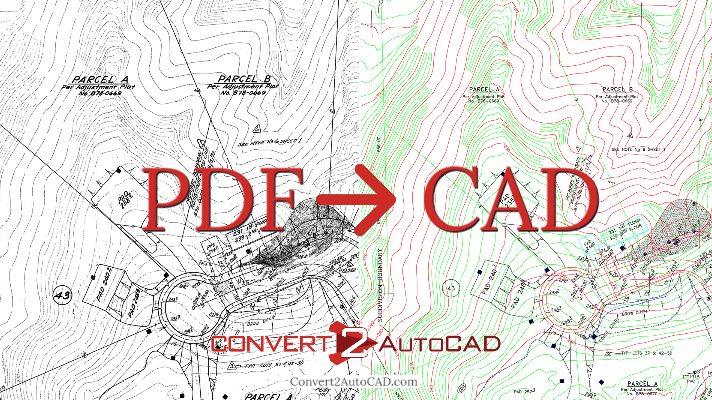
PDF to CAD is a revolutionary online service that involves skilled drafters to deliver a precise AutoCAD file, for your business. PDF is the print industry standard for document scanning, sharing and printing. It long overtook formats like TIFF and JPG a long time ago, with it’s fine detail, great compression, and font embedding capabilities. You may have PDF files of plans that you need to remodel, or would like to archive. CAD is the industry standard for architectural and engineering design. Developed by AutoDesk over 35 years ago, it is now the benchmark for vector design. It can include blocks and layers.
A personal touch
We take your PDF files and redraw them in AutoCAD. That’s right, a real human draws your files. This lets us separate the layers like doors, walls, hardscape, dimensions, and so on. Convert2AutoCAD does not just run it through software and output the file. The advantage is huge. You can now make changes to specific walls, and doors easily. This leaves you with a clean file that will look professional for years to come. PDF to CAD is a service that will make you money.
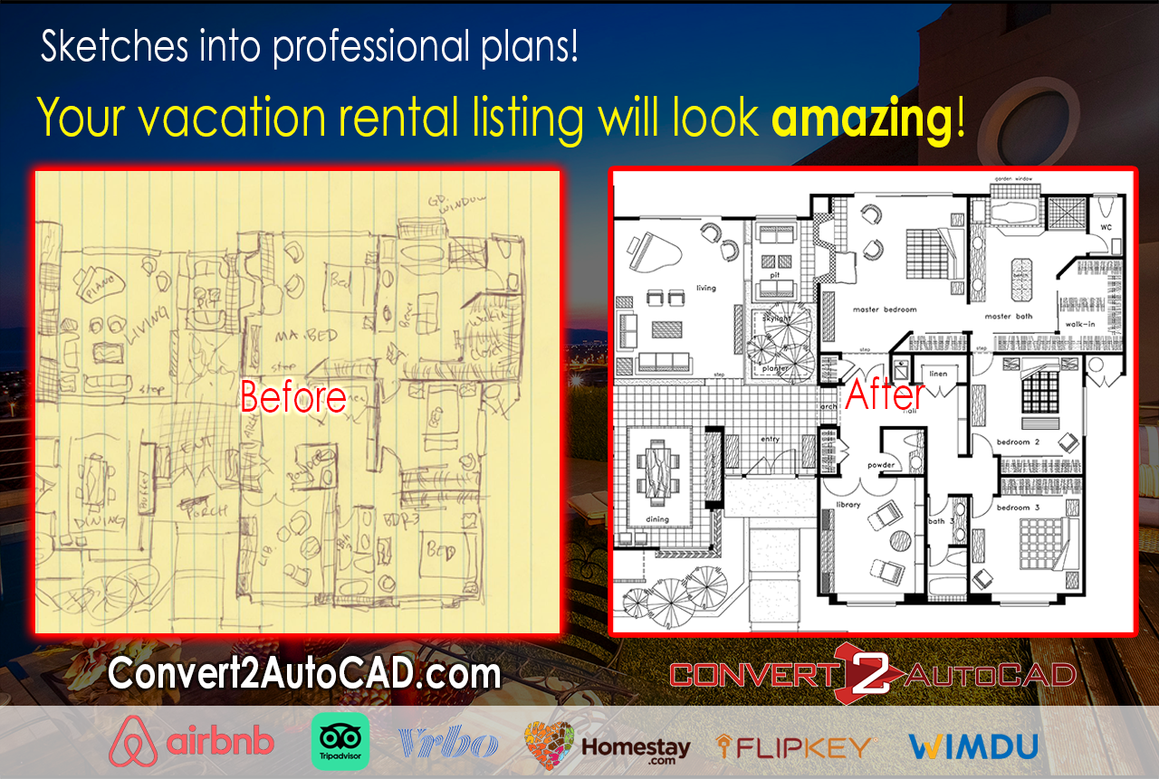
Have a professional vacation rental listing
This service can also be useful if you are an Airbnb host, who need floor plans for your listing. The professional floor plans will lead to more reservations, and more income for you. You can even roughly hand draw a plan, and we can have give you a professional looking plan on JPG, PNG, or GIF. Your short-term rental will make you more money, with a small investment in a professional floor plan. This gives your Airbnb or Tripadvisor vacation rental a higher chance of staying booked.
Essential for remodels
Are you an architect, contractor or interior designer that does remodels? Take old plans and have them converted to vector by us, to give you a fast and easy way to make changes. This can save you lots of time, allowing you more time to take on more jobs. Remodels have never been so easy.
Quick turnaround and affordable
We have a turnaround time in as little as 24 hours. This is an incredible feat, given that some designs are very complicated. Pricing is very reasonable, starting at only $85 per sheet. We can also handle large bulk conversions of over 100 sheets. To get a fast, free quote, submit your files.
Differences between PDF and DWG
Here is a chart explaining the two file types, and what they are used for
Should we ignore modern and non-Western architectural styles in all future federal buildings?
Standardization of Art
Federal buildings are not standardized. They come in many shapes, and styles. You will find Romanesque Revival, Greek Revival, Gothic Revival and many other classic western styles. These are known for stone block, steep columns, vaulted ceilings, and arched doorways and windows. They often have towers and are decorative. Art deco style was popular in the early 1900’s and we can see that in many federal buildings, including the Federal Courthouse in South Bend, Indiana. Later we had modern styles like brutalist and deconstructivist architecture.
President Donald Trump has proposed an exectuive order that could ban modern styles like brutalist and deconstructivist architecture for federal buildings. It could also ban non-western style architecture styles from Asia, Africa and the Middle East. This would severely limit how our buildings would look.
Build more, or restore?
The money used to build these new buildings might be better off spent preserving and restoring current federal buildings. There are many in disrepair, and preserving history could be money better spent. I do enjoy the classic western styles, but also enjoy the modern styles. To limit our creativity, is to limit our thoughts. The United States of America is bout hard work, creativity, and pushing boundaries.
Federal Courthouse in South Bend
Edith Green Wendell Wyatt Federal Building
Rochester New York Federal Building
Pueblo Colorado Federal Building
San Francisco Federal Building
About Convert to AutoCAD
Save yourself hours, days, and weeks redrafting old plans. We take your PDF, JPG, GIF, or TIF file, and convert it to fully layered AutoCAD DWG files. We also work with Revit and Sketchup. Our professional drafters can have your conversion done for you in as little as 24-hours. For a free, immediate quote, submit your files on our order form.
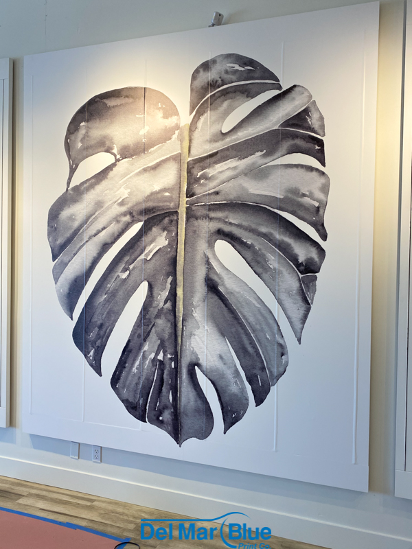
Our partners over at Del Mar Blue Print are now offering custom printed wall vinyl. Wall vinyl is is a large graphic that clings to walls, and can be printed with any image, text, artwork, or logo imaginable. Similar to wall paper, but more durable, and easier to remove. This could be a game changer for your office, home, retail space or restaurant. Check out more on this service at the Del Mar Blue Print blog.
About Del Mar Blue Print
For over 40 years, Del Mar Blue Print have been servicing San Diego County with banner printing, reprographics, graphic design, and marketing services. They take pride in their attention to detail, cutting edge technology, and elite customer service. From business cards, to blue prints, Del Mar Blue Print is your one stop print shop.
What is Convert2AutoCAD?
We can take your image and convert it to a fully layered DWG AutoCAD file in as little as 24-hours. Have a PDF you would like converted to AutoCAD? Send it over for a free quote!
You list out your property on short-term rental websites like Airbnb, Tripadvisor and Vrbo. You know how important good photos, a description, and pricing are to getting the most for your rental. Do you have a good floor plan? We can take a sketch that you make, and turn it into a professional floor plan in AutoCAD. We take your hand drawn sketch, and design it all in AutoCAD by our professional drafters. This includes walls, rooms, furniture, fixtures, lighting, patios, and landscaping.
Why do I need a floor plan for my Airbnb listing?
It’s not easy to stand out from the competition, but you can with a professional floor plan on your listing. This gives the customer an accurate vision of what your location offers. If you take a few measurement, we can also show the dimensions in the floor plan. Show your amenities with a professional design.
I already have plans, but they are old and hard to read.
Do you have old plans already? Take a photo or have them scanned, and we can also turn those into professional plans! We can send you a JPG or PNG file that will fit perfectly in your listing. We can turn it around in as little as 24 hours for pricing starting at $85! For this price, you can’t go wrong! Contact us for an exact quote.
Located in San Diego, California, we have been offering drafting and print services for over 40 years. Accuracy and customer service are top priorities. Convert2AutoCAD services are very affordable, and can help you rent out your home. We are a team of experienced drafters, that will create a clean, professional AutoCAD plan to use on your rental listing. Feel free to contact us for a free quote.
Single sheet or thousands of pages, we can handle all size orders
Convert your scans to CAD. We get orders ranging from a small sketch, to hundreds of sheets for large municipalities. Our rates are the lowest and we offer discounts of up to 25% off your entire order if you order 8 sheets in a single order. This can save you anywhere from $200 per job, to thousands in savings! Do you have a project that is hundred of pages? We can schedule out a plan to have at least 100 pages done per month. We have a dedicated team to have the work done for you quickly, and accurately.
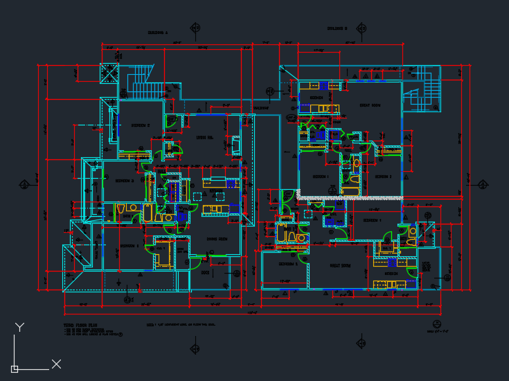
Here is an example of a CAD file from a hand drawn plan scan.
How do we do it?
We work with large government municipalities, or small architects. We will give you a quote, and estimated time of completion. How are we able to do it? We have a team of skilled drafters that redraw your design in AutoCAD, giving you the a fully-layered 2D image to work with. Convert2AutoCAD can also provide 3D designs in Revit, Google Sketchup and any other BIM program you need.
PDF to CAD
Send over your PDF plan to have it converted to fully layered vector CAD file.
We use best practices for layer names, but you may not want to on your scans to cad project. Isn’t it nice to name your layers so they make sense to you? We can use your layer names and colors so they can easily match the rest of your work. Some people like very descriptive layer names, and some just like a few letters. Send us a screenshot of your normal layer names, and we can use that on all of your CAD conversion projects with us.
Here you can see some custom layer names and colors
Need changes? Grab a red pen!
We understand you may want to add a door, or take down a wall. Just simply grab a red pen, or any paint program and write your changes on the plan. We will make those changes to the CAD file for you. We have done whole home remodels this way.
Work with us!
It would be a pleasure to work with you on your next project. Not on a project? Feel free to contact us so we can let you know how we can improve your work flow, and save you valuable time and money.
PDF to CAD
Send over your PDF plan to have it converted to fully layered vector CAD file.
Here is a handy AutoCAD release version history, starting from 1.0 in 1982. AutoCAD is the standard in 2D drafting and design. It’s still used by millions of architects, engineers and designers. Developed by AutoDesk, AutoCAD is the industry standard for 2D design. The native file is normally *.dwg. If you are interested in converting PDF, JPG, TIF, or GIF to AutoCAD, send it to us.
AutoCAD 1.0 December 1982 (Release 1) AutoCAD 1.2 April 1983 (Release 2) AutoCAD 1.3 August 1983 (Release 3) AutoCAD 1.4 October 1983 (Release 4) AutoCAD 2.0 October 1984 (Release 5) AutoCAD 2.1 May 1985 (Release 6) AutoCAD 2.5 June 1986 (Release 7) AutoCAD 2.6 April 1987 (Release 8) AutoCAD R9 September 1987 codename White Album (Release 9) AutoCAD R10 October 1988 codename Abbey Road (Release 10) AutoCAD R11 October 1990 codename Let it Be (Release 11) AutoCAD R12 June 1992 (Release 12) AutoCAD R13 November 1994 (Release 13) AutoCAD R14 February 1997 codename Sedona and Pinetop for 14.01 (Release 14) AutoCAD 2000 March 1999 codename Tahoe (Release 15) AutoCAD 2000i July 2000 codename Banff (Release 16) AutoCAD 2002 June 2001 codename Kirkland (Release 17) AutoCAD 2004 March 2003 codename Reddeer (Release 18) AutoCAD 2005 March 2004 codename Neo (Release 19) AutoCAD 2006 March 2005 codename Rio (Release 20) AutoCAD 2007 March 2006 codename Postrio (Release 21) AutoCAD 2008 March 2007 codename Spago (Release 22) AutoCAD 2009 March 2008 codename Raptor (Release 23) AutoCAD 2010 March 2009 codename Gator (Release 24) AutoCAD 2011 March 2010 codename Hammer (Release 25) AutoCAD 2012 March 2011 codename Ironman (Release 26) AutoCAD 2013 March 2012 codename Jaws (Release 27) AutoCAD 2014 March 2013 codename Keystone (Release 28) AutoCAD 2015 March 2014 codename Longbow (Release 29) AutoCAD 2016 March 2015 codename Maestro (Release 30) AutoCAD 2017 March 2016 codename Nautilus (Release 31) AutoCAD 2018 March 2017 codename Omega (Release 32) AutoCAD 2019 April 2018 codename Pi (Release 33) AutoCAD for Mac Releases:
PDF to CAD
Send over your PDF plan to have it converted to fully layered vector CAD file.
AutoCAD for Mac June 1992 AutoCAD for Mac R13 AutoCAD 2011 for Mac October 2010 (SledgeHammer) AutoCAD 2012 for Mac August 2011 (Iron Maiden) AutoCAD LT 2012 for Mac August 2011 (Ferris) AutoCAD LT 2013 for Mac August 2012 AutoCAD 2013 for Mac March 2012 (Jaws) AutoCAD LT 2014 for Mac AutoCAD 2014 for Mac (Sandstone) AutoCAD 2015 for Mac (Lightsaber) AutoCAD 2016 for Mac (Mandalore) AutoCAD 2017 for Mac (Naboo) AutoCAD 2018 for Mac Nov 2017 AutoCAD WS
AutoCAD WS / AutoCAD WS Mobile September 2010 AutoCAD WS for Mac August 2011
AutoCAD Architecture “ACA”
AutoCAD Architectural Desktop 1 October 1998 codename Portsmouth (Release 1)
AutoCAD Architectural Desktop 2 July 1999 codename Mannheim (Release 2)
AutoCAD Architectural Desktop 2i July 2000 codename iMannheim (Release 3)
AutoCAD Architectural Desktop 3 March 2001 codename Cleveland (Release 4)
AutoCAD Architectural Desktop 3.3 March 2001 codename Palm Beach (Release 5)
Autodesk Architectural Desktop 2004 March 2003 codename Exeter (Release 6)
Autodesk Architectural Desktop 2005 March 2004 3/17/2004 codename Juneau (Release 7)
Autodesk Architectural Desktop 2006 March 2005 codename codename Rialto (Release 8)
Autodesk Architectural Desktop 2007 March 2006 codename codename Kyoto (Release 9)
AutoCAD Architecture 2008 March 2007 codename codename Kiasma (Release 10)
AutoCAD Architecture 2009 March 2008 codename codename Tate (Release 11)
AutoCAD Architecture 2010 March 2009 codename Botta (Release 12)
AutoCAD Architecture 2011 codename March 2010 codename Potala (Release 13)
AutoCAD Architecture 2012 March 2011 (Release 14)
PDF to CAD
Send over your PDF plan to have it converted to fully layered vector CAD file.
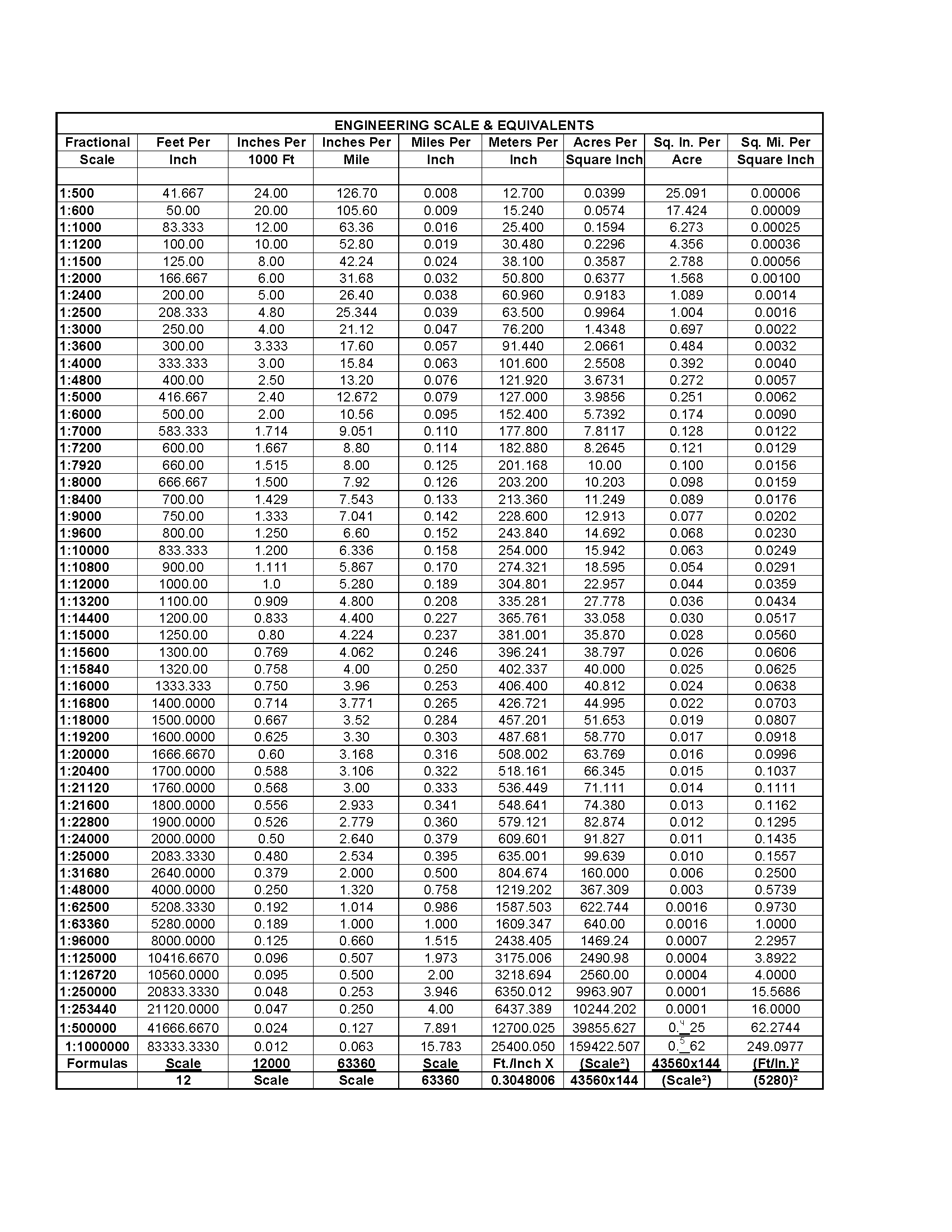
We have a handy PDF file showing engineering and map scales, and their decimal and fractional equivalents. This is an easy to use chart so you can convert to different scales. We have found this useful for converting fractional scale to feet per inch, inches per 1000 feet, inches per mile, meters per inch, acres per square inch, square inches per acre, and square mile per square inch.
Download a printable PDF version of this chart at the link below.
Every year, Autodesk comes out with version updates their products, including the industry leading architectural 2D design platform, AutoCAD. There are some new integrations, tools, and features to help your work flow, and save you time. Below are some of the new features that you will find in AutoCAD 2020. If you are looking for alternatives to using AutoCAD, we have compiled a list.
Quick Measure Tool
This tool allows you to quickly display measurments by moving your curser anywyere on the drawing. Just select the tool and it will display dimensions as you move. This will be an ideal way to check your work. Distances, dimensions and angles are all displayed as you move your mouse over and between objects.
New Dark Theme
This new theme is much easier on the eyes than the traditional black background theme. The dark theme now has a modern dark blue interface that will help fight fatigue and is more comfortable to view on your computer or phone.
Blocks Palette
This new feature makes choosing and finding blocks much easier. Includes visual galleries, so you no longer need the names memorized. This also helps organize your blocks by displaying recently used blocks, so you do not have to search every time.
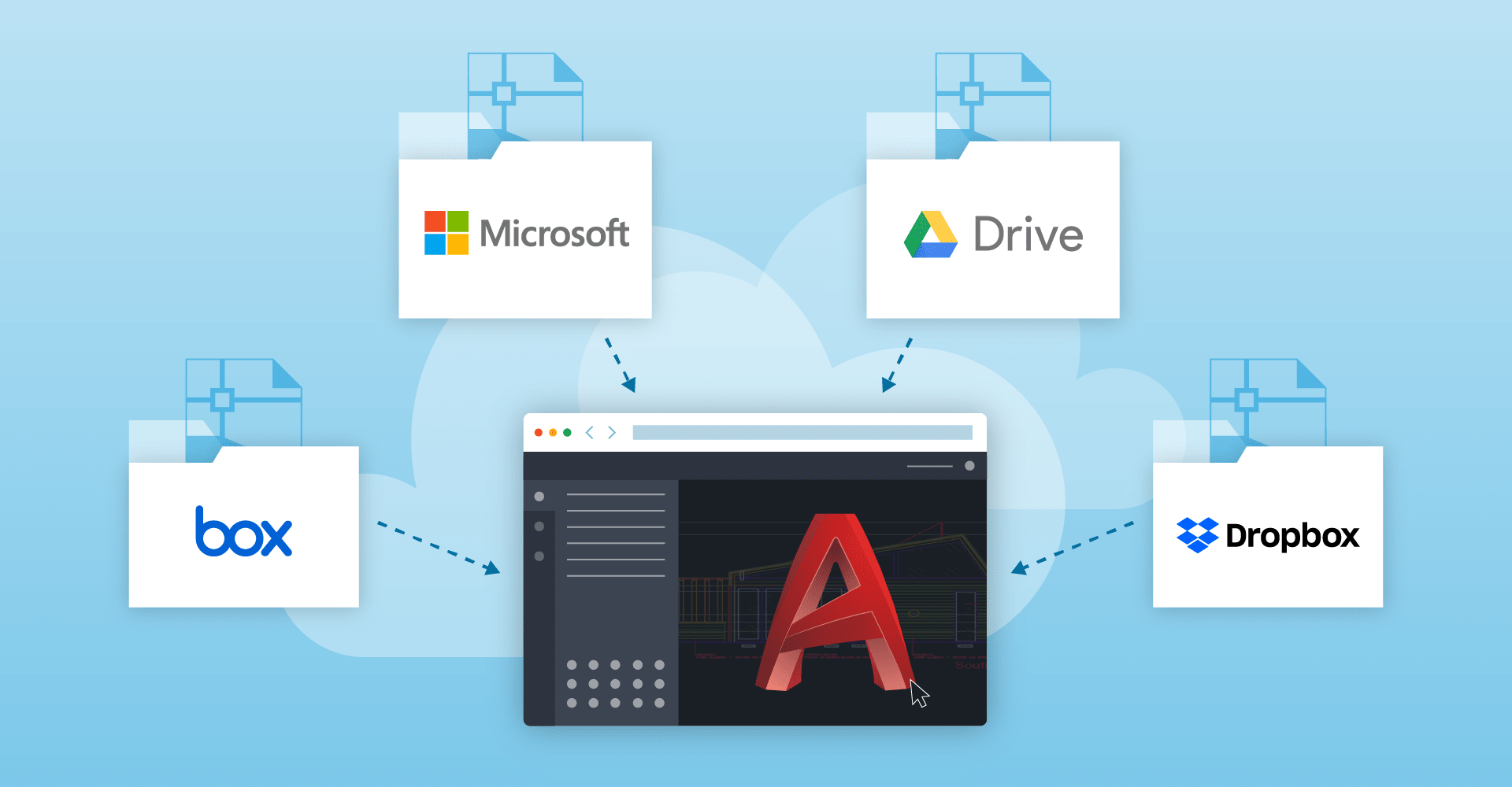
AutoCAD 2020 on the Cloud
You can now work out of the cloud with partnerships with Microsoft and Box. Box (formerly known as Dropbox) and Microsoft with their OneDrive service can let you work from any location. This can also help you collaborate on projects. Back your projects up, so you don’t have to worry about failed hardware.
DWG Compare
Easily compare two versions of a drawing, without having to leave your current window. Now you have the ability to toggle on and off the comparison within the new DWG Compare toolbar.
If you would like to learn more about the new features in AutoCAD 2020, check out the list of features on the AutoCAD website. At Convert2AutoCAD, we can take your drawings, and converted them to layered vector DWG files. Contact us for pricing and information.
You don’t need to go to a university to learn AutoCAD
Today we are going to discuss where to learn AutoCAD online. These are good if you want to give AutoCAD a try, or are an architect, engineer or drafter, that wants to move away from hand drawn plans, and move into digital CAD drafting. Some of these are free, some of them are subscription based. These are not accredited courses. Before starting, you need CAD software, and AutoCAD by Autodesk is the gold standard. You can download a free educational version of AutoCAD. You can also try some CAD alternatives.
Now lets get down to the list:
LinkedIn Learning$29.99 a month – LinkedIn Learning (formally Lynda.com) has lots of video courses and tutorials, for the beginner and novice alike. I have tried their courses, and their video format is easy to follow.
MyCadSite.comFree – This is a real cool set of lessons that include text, photos and videos. This is a fantastic resource for beginners and novice skill levels. You don’t need to sign up for an account, all the material is there for the public.
Tutorial45Free – This is a great site for beginners. It includes a lot of step-by-step instructions with screenshots.
CadTutorFree – Some great video instruction, though the material is a little dated, I think most of the information is still very useful.
Skillshare$15.00 a month – Decent video courses geared towards beginners to help you learn AutoCAD.
CAD in BlackFree – This is a YouTube channel consisting of many video tutorials on AutoCAD.
I hope this list helps you learn autocad online. I also hope it helps some of you get into AutoCAD, or expand your current knowledge of CAD. As always, if you need any files converted from PDF to CAD, send them to me for a free quote.
Bulk discounts are given to our customers who order 8 or more AutoCAD conversions in a single order. Send us an order of at least 8 sheets, and we will give you 15% off your entire order!
We know sometimes you have a lot of plans to have converted at a time. This is an even bigger reason to send them all into us, and receive a discount. Do you have a major project of at least 100 pages to convert? We can offer an even deeper discount for you. Our team of skilled drafters can create accurate, and professional AutoCAD DWG files for you to work with.
Who works with us?
At Convert2AutoCAD, we have worked with general contractors, architects, engineers, city, state, and federal government, healthcare, education and home owners. We can convert from PDF, TIF, Microstation, JPG, PLT, and just about any file format you can think of.
Get a free quote!
Send your files to us for a free same day quote! We will give you a price and estimated completion time. Order 8 or more AutoCAD conversions, and you will receive bulk discounts. Give us a call us at (858) 755-5134.
I am often asked about alternatives to AutoCAD. The long running computer aided design program (CAD) AutoCAD has been the standard for 2D design for over 30 years. It was created by AutoDesk in 1982, and took the design world by storm. One issue people have with it, is it’s hefty price. With a yearly price tag of over $1,500 a year, it’s easy to see why people would be looking for a cheaper alternative.
Many people ask me if there is any alternatives to AutoCAD? The answer is yes, there is. If you have any suggestions, I would love to hear from you. Here’s a list of those programs below:
DraftSight – A free CAD program, with some features needing a paid license.
FreeCAD – A free open source 3D CAD design program.
SketchUp – Currently owned by Google, this program can help you work in 2D and 3D. It is free for non-commercial use.
BricsCAD – A professional design program, with paid licensing.
SolveSpace – Free, open source 2D and 3D CAD for modeling parts.
NanoCAD – 2D and 3D design program that is fairly inexpensive.
We happen to use AutoCAD, and can help you with your design project. If you would like to have your PDF plans converted to AutoCAD DWG, submit them here for a free quote.
This also works if you want to convert imperial to metric
We often get requests to convert an architectural or engineering CAD drawing from metric to imperial measurements. Converting from metric to imperial in AutoCAD is easier than you might think. This may seem complicated, but it really isn’t. There are a few quick commands that makes it pain free. There are two methods to accomplish this.
Using the INSERT command:
Create a new blank drawing using a template that is in the target units (for example acadiso.dwt for Metric or acad.dwt for Imperial).
At the command line, enter INSERT.
In the Insert dialog box, browse to the original DWG file.
Check the box to Explode.
Click OK and specify an insertion point.
PDF to CAD
Send over your PDF plan to have it converted to fully layered vector CAD file.
We can work in metric! Today we had a call from a gentleman in Australia who said our website does not mention metric. We can convert in metric or imperial measurements, and it is no extra charge! We are in the USA, but we really love metric. If you would like to have a plan converted to a layered AutoCAD file, send over an image of any file type, and we will respond quickly with a quote.
If you would like to convert metric to imperial, or imperial to metric, check out our handy conversion chart. For a metric to imperial online calculator check out this one from metric-conversions.org.
We can convert your plan in metric or imperial measurements.
Here is a list of commands, hotkeys and keyboard shortcuts for the Autodesk 3D design program Revit. If you would like to learn more about Revit and AutoCAD services, contact us.
Annotate
DI
ALIGNED DIMENSION / Creates an aligned dimension.
DL
DETAIL LINE / Creates view-specific lines.
EL
SPOT ELEVATION / Displays the elevation of a selected point.
FR
FIND/REPLACE / Find and replace.
GP
MODEL GROUP:CREATE GROUP; DETAIL GROUP:CREATE GROUP / Creates a group of elements.
RT
TAG ROOM; ROOM TAG / Tags the selected room.
TG
TAG BY CATEGORY / Applies tags to elements based on their categories.
TX
TEXT / Adds text.
Analyze
AA
ADJUST ANALYTICAL MODEL / Adjusts the analytical model of the structural member in relation to those of the elements to which it joins.
DC
CHECK DUCT SYSTEMS / Examines the mechanical systems in a project to verify that each system is assigned to a userdefined system, and properly connected.
EC
CHECK CIRCUITS / Verifies all circuits for proper connections to panels and valid system assignments.
LD
LOADS / Applies point, line and area loads to a model.
LO
HEATING AND COOLING LOADS / Prepares a heating and cooling load analysis report based on an existing building model.
PC
CHECK PIPE SYSTEMS / Examines the piping systems in a project to verify that each system is assigned to a user-defined system, and properly connected.
PS
PANEL SCHEDULES / Generates a panel schedule for a specific panel.
RA
RESET ANALYTICAL MODEL / Restores the analytical model alignment methods to auto-detect.
Architecture
CL
COLUMN; STRUCTURAL COLUMN / Adds a vertical load-bearing element to the building model.
CM
PLACE A COMPONENT / Place a component.
DR
DOOR / Adds a door to the building model.
GR
GRID / Places column grid lines in the building design.
LL
LEVEL / Places a level in view.
RM
ROOM / Creates a room bounded by model elements and separation lines.
RP
REFERENCE PLANE / Creates a reference plane using drawing tools.
RT
TAG ROOM; ROOM TAG / Tags the selected room.
SB
FLOOR:FLOOR: STRUCTURAL / Adds structural floors to a building model.
WA
WALL; WALL:WALL: ARCHITECTURAL / Creates a non-bearing wall or a structural wall in the building model.
WN
WINDOW / Places a window in a wall or skylight in a roof.
Collaborate
ER
EDITING REQUESTS / Displays a list of usersí requests to borrow elements in worksets, as well as pending requests.
RL or RW
RELOAD LATEST / Loads the latest version of the central model.
Context Menu
MP
MOVE TO PROJECT / Move the model relative to a shared coordinate system.
R3
DEFINE A NEW CENTER OF ROTATION / Relocates center of rotation when rotating elements.
RA
RESTORE ALL EXCLUDED / Restores all excluded parts and elements.
RB
RESTORE EXCLUDED MEMBER / Restores an excluded member.
RC
REPEAT LAST COMMAND / Repeats the last command.
SA
SELECT ALL INSTANCES: IN ENTIRE PROJECT / Selects all of the elements that are similar to the selected element in the current view, or throughout the project.
Contextual Tabs
//
DIVIDE SURFACE / Applies a division grid along a surface in a conceptual design.
AA
ADJUST ANALYTICAL MODEL / Adjusts the analytical model of the structural member in relation to those of the elements to which it joins.
AD
ATTACH DETAIL GROUP / Creates an attached detail group.
AP
ADD TO GROUP / Adds elements to a group.
BS
STRUCTURAL BEAM SYSTEM; AUTOMATIC BEAM SYSTEM / Creates a layout that is used to control the number and spacing of a series of parallel beams.
CG
CANCEL / Cancels an action.
DI
ALIGNED DIMENSION / Creates an aligned dimension.
EG
EDIT GROUP / Edits a group.
EL
SPOT ELEVATION / Displays the elevation of a selected point.
EP
EDIT PAR / Edits a part element.
EU
UNHIDE ELEMENT / Enables a hidden element to appear in view.
EW
EDIT WITNESS LINES / Edits a witness line.
FG
FINISH / Finishes editing a group.
HT
SHOW HELP TOOLTIP / Displays the Help Tooltip.
JP
JUSTIFICATION POINTS / Sets a justification point for relocating elements.
JY
ZOFFSET / Offsets an element in the z direction.
JZ
SHOW HELP TOOLTIP / Displays the Help Tooltip.
LI
MODEL LINE; BOUNDARY LINE; REBAR LINE / Places a new line.
PP or CTRL-1 or VP
PROPERTIES; TOGGLE PROPERTIES PALETTE / Toggles the Properties palette.
RA
RESTORE ALL EXCLUDED / Restores all excluded parts and elements.
RG
REMOVE FROM GROUP / Removes elements from a group.
RH
TOGGLE REVEAL HIDDEN ELEMENTS MODE / Toggles the Reveal Hidden Elements Mode.
RP
REFERENCE PLANE / Creates a reference plane using drawing tools.
UG
UNGROUP / Ungroups members of a group.
VU
UNHIDE CATEGORY / Enables a hidden category to appear in view.
Create
CM
PLACE A COMPONENT / Place a component.
D
ALIGNED DIMENSION / Creates an aligned dimension.
FR
FIND/REPLACE / Find and replace.
GP
MODEL GROUP:CREATE GROUP; DETAIL GROUP:CREATE GROUP / Creates a group of elements.
LI
MODEL LINE; BOUNDARY LINE; REBAR LINE / Places a new line.
LL
LEVEL / Places a level in view.
MD
MODIFY / Enters selection mode to select elements to modify.
PP or CTRL-1 or VP
PROPERTIES; TOGGLE PROPERTIES PALETTE / Toggles the Properties palette.
RP
REFERENCE PLANE / Creates a reference plane using drawing tools.
TX
TEXT / Adds text
Manage
ES
MEP SETTINGS:ELECTRICAL SETTINGS / Accesses dialog box to specify wiring parameters, voltages definitions, distribution systems, cable tray and conduit settings, and load calculation and circuit numbering settings.
MS
MEP SETTINGS:MECHANICAL SETTINGS / Accesses dialog box to configure component sizes, and the behavior and appearance of the mechanical systems.
SU
ADDITIONAL SETTINGS:SUN SETTINGS / Opens the sun settings dialog box.
UN
PROJECT UNITS / Opens the Project Units tool.
Modify
AL
ALIGN / Aligns one or more elements with selected element.
AR
ARRAY / Creates a linear or radial array of selected elements.
CO or CC
COPY / Copies selected element(s).
CP
COPE; APPLY COPING / Applies coping to steel beam or columns.
CS
CREATE SIMILAR / Creates an element of the same type as the selected element.
DE
DELETE / Removes selected element(s) from the building model.
DI
ALIGNED DIMENSION / Creates an aligned dimension.
DM
MIRROR – DRAW AXIS / Reverses the position of a selected model element, using a user-generated line as the mirror axis.
EH
HIDE IN VIEW:HIDE ELEMENTS / Hides an element from view.
EL
SPOT ELEVATION / Displays the elevation of a selected point.
EOD
OVERRIDE GRAPHICS IN VIEW:OVERRIDE BY ELEMENT / Changes the graphic display settings for selected elements in the current view.
LI
MODEL LINE; BOUNDARY LINE; REBAR LINE / Places a new line.
LW
LINEWORK / Overrides the line style of selected line in the active view only.
MA
MATCH TYPE PROPERTIES / Opens the Match Type tool to convert one or more elements to match the type assigned to another element.
MM
MIRROR – PICK AXIS / Reverses the position of a selected model element, using a selected line as the mirror axis.
MV
MOVE / Moves a selected element.
OF
OFFSET / Moves a selected model line, detail line, wall, or beam a specified distance perpendicular to its length.
PN
PIN / Locks a model element in place.
PP or CTRL-1 or VP
PROPERTIES; TOGGLE PROPERTIES PALETTE / Toggles the Properties palette.
PT
PAINT / Opens the Paint tool.
RC
COPE:REMOVE COPING / Removes coping.
RE
SCALE / Resizes the selected element.
RO
ROTATE / Rotates selected element around an axis.
RP
REFERENCE PLANE / Creates a reference plane using drawing tools.
SF
SPLIT FACE / Divides the face of an element into regions for application of different materials.
SL
SPLIT ELEMENT / Cuts an element (such as a wall or line) at a selected point.
TR
TRIM/EXTEND TO CORNER / Trims or extend one or more elements to form a corner.
UP
UNPIN / Unpins an element that is locked in position or an element that is driven by its host system.
VH
HIDE IN VIEW:HIDE CATEGORY / Hides an element category from view.
Navigation Bar
32
2D MODE / Navigates the view using only 2D navigation options.
3F
FLY MODE / Simulates flying through a model.
3O
OBJECT MODE / Navigates and reorients the view in the direction of the controller cap.
3W
WALK MODE / Simulates walking through a model.
ZA
ZOOM ALL TO FIT / Zooms to fit all in view.
ZE or ZF or ZX
ZOOM TO FIT / Zooms to fit.
ZO or ZV
ZOOM OUT(2X) / Zooms out the project view by 2X.
ZP or ZC
PREVIOUS PAN/ZOOM / Returns to previous pan or zoom.l
ZR or ZZ
ZOOM IN REGION / Zooms to a region.
ZS
ZOOM SHEET SIZE / Zooms to sheet size.
Snaps
PC
SNAP TO POINT CLOUDS / Snaps to point cloud.
SC
CENTERS / Snaps to center
SE
ENDPOINTS / Snaps to endpoints.
SI
INTERSECTIONS / Snaps to intersection.
SM
MIDPOINTS / Snaps to midpoint.
SN
NEAREST / Snaps to nearest.
SO
SNAPS OFF / Turns snaps off.
SP
PERPENDICULAR / Snaps to perpendicular.
SQ
QUADRANTS / Snaps to quadrant.
SR
SNAP TO REMOTE OBJECTS / Snaps to objects that are not near the element.
SS
TURN OVERRIDE OFF / Turns off override feature.
ST
TANGENTS / Snaps to tangent.
SW
WORK PLANE GRID / Snaps to the work plane grid.
SX
POINTS / Snaps to points.
Structure
BM
STRUCTURAL FRAMING: BEAM / Adds a load-bearing structural beam element to the building model.
BR
STRUCTURAL FRAMING: BRACE / Adds diagonal members that are connected to beams and columns.
BS
STRUCTURAL BEAM SYSTEM; AUTOMATIC BEAM SYSTEM / Creates a layout that is used to control the number and spacing of a series of parallel beams.
CL
COLUMN; STRUCTURAL COLUMN / Adds a vertical load-bearing element to the building model.
CM
PLACE A COMPONENT / Place a component.
FT
STRUCTURAL FOUNDATION: WALL / Creates a wall foundation for the building model.
GR
GRID / Places column grid lines in the building design.
LL
LEVEL / Places a level in view.
RN
REINFORCEMENT NUMBERS / Defines or edits numbering sequences by partition for rebar and fabric sheets.
RP
REFERENCE PLANE / Creates a reference plane using drawing tools.
SB
FLOOR:FLOOR: STRUCTURAL / Adds structural floors to a building model.
WA
WALL; WALL:WALL: ARCHITECTURAL / Creates a non-bearing wall or a structural wall in the building model.
System
AT
AIR TERMINAL / Places a register, grille or diffuser.
CM
PLACE A COMPONENT / Place a component.
CN
CONDUIT / Draws a rigid conduit run.
CT
CABLE TRAY / Draws a cable tray run.
CV
CONVERT TO FLEX DUCT / Converts a section of rigid duct to flexible duct.
DA
DUCT ACCESSORY / Adds duct accessories, such as dampers, in duct systems.
DF
DUCT FITTING / Places duct fittings (elbows, tees, end caps, and so on) in duct systems.
DT
DUCT / Draws ductwork in the building model.
EE
ELECTRICAL EQUIPMENT / Places electrical equipment, such as panels and switch gear.
EW
ARC WIRE / Draws an arced wire run.
FD
FLEX DUCT / Draws flexible ductwork in the building model.
FP
FLEX PIPE / Draws flexible pipes.
LF
LIGHTING FIXTURE / Adds a lighting fixture element.
ME
MECHANICAL EQUIPMENT / Places mechanical equipment such as boilers, furnaces or fans.
NF
CONDUIT FITTING / Places conduit fittings.
PA
PIPE ACCESSORY / Adds pipe accessories.
PF
PIPE FITTING / Draws a pipe fitting in a piping system.
PI
PIPE / Draws rigid piping.
PX
PLUMBING FIXTURE / Places a plumbing fixture.
RP
REFERENCE PLANE / Creates a reference plane using drawing tools.
SK
SPRINKLER / Places a sprinkler
TF
CABLE TRAY FITTING / Places cable tray fittings.
View
FN9
SYSTEM BROWSER / Finds components that are not assigned to a system.
KS
KEYBOARD SHORTCUTS / Assigns key sequences to tools.
PP or CTRL-1 or VP
PROPERTIES; TOGGLE PROPERTIES PALETTE / Toggles the Properties palette.
RD
RENDER IN CLOUD / Renders 3D views online.
RG
RENDER GALLERY / Enables access to multiple versions of renderings, render images as panoramas, change rendering quality, and apply background environments to rendered scenes.
RR
RENDER / Creates a photorealistic image of the building model.
TL
THIN LINES / Displays all lines on the screen as a single width, regardless of zoom level.
VG or VV
VISIBILITY/GRAPHICS / Controls the visibility and graphic display of model elements, datum elements, and viewspecific elements for each view in a project.
WC
CASCADE WINDOWS / Arranges all open windows in a series in the drawing area.
WT
TILE WINDOWS / See all open views at the same time.
View Control Bar
CX
TOGGLE REVEAL CONSTRAINTS MODE / Toggles the constraints in a view.
GD
GRAPHIC DISPLAY OPTIONS / Opens the Graphics dialog box.
HC
HIDE CATEGORY / Hides all selected categories in the view.
HH
HIDE ELEMENT / Hides an element from view.
HI
ISOLATE ELEMENT / Isolates selected elements.
HL
HIDDEN LINE / Displays the image with all edges and lines drawn except those obstructed by surfaces.
HR
RESET TEMPORARY HIDE/ISOLATE / Restores any temporarily hidden elements or categories.
IC
ISOLATE CATEGORY / Isolates selected categories.
RD
RENDER IN CLOUD / Renders 3D views online.
RG
RENDER GALLERY / Enables access to multiple versions of renderings, render images as panoramas, change rendering quality, and apply background environments to rendered scenes.
RH
TOGGLE REVEAL HIDDEN ELEMENTS MODE / Toggles the Reveal Hidden Elements Mode.
RR
RENDER / Creates a photorealistic image of the building model.
RY
RAY TRACE / Opens Ray Trace visual style, enabling a photorealistic rendering mode that allows panning and zooming around the model.
SD
SHADED WITH EDGES / Applies a shaded edge.
WF
WIREFRAME / Displays the image of the model with all edges and lines drawn, but with no surfaces drawn.
A listing of all architects in the AIA (American Institute of Architects)
Finding an architect in your area just got easier. The AIA has a complete searchable listing of all of its members by name, zip code, city, state, and building type. This makes it easy to find any architect in the United States.
About the American Institute of Architects
The American Institute of Architects has been around for over 150 years and has over 90,000 members, making it the largest architect organization in the United States. We are proud supporters by sponsoring events from local chapters AIA Palomar, and San Diego. To read more about the structure and history, check out the their Wikipedia page.
About Convert2AutoCAD
We convert paper or PDF plans to fully layered AutoCAD DWG files. For a free quote send over your files. Convert2AutoCAD is part of the Del Mar Blue family. We are a small business located in California.
I have a sheet that is not to scale, but I want it to scale
You can learn to scale an architectural plan to any scale you want
Many times, we receive plans from customers that are reduced to a page size, or are to a scale that they can’t use. For example, they have a printout of a plan that is on a small sheet, say size 8.5×11 inches. Well, they want that same page enlarged to the full scale that it was originally. In this example we are enlarging a sheet that we don’t know the scale, to 1 inch = 4 feet, otherwise known as 1/4 scale. This sample works only as long as the proportions are in tact. If the image has been stretched in any direction, this method will not work and you will have to edit it in image editing software like Adobe Photoshop to get all dimensions to scale. Since I am in the U.S., I will be showing you this procedure using imperial measurements.
Here are the things that you will need.
An architectural scale
A regular inches ruler
Scratch paper
A calculator
Supplies you will need to enlarge and reduce your plans to scale.
We need the sheet that you are printing from to be printed out. Be sure that when you print it, to select “Actual Size” and not “Fit.” This will ensure the sheet you are measuring does not change when you print it.
The formula we use for this is simple.
WANT ÷ IS x 100 = percentage
WANT = size you want that dimension to measure
IS = the size that dimension currently measures to
PERCENTAGE = the percentage to enlarge or reduce the image
Find a large dimension on the sheet that is a full number in feet. Try to avoid a dimension like 12’9”. In my case, I have found a dimension that shows 40-feet.
Measure your original sheet that you are trying to enlarge
PDF to CAD
Send over your PDF plan to have it converted to fully layered vector CAD file.
Take a measurement of that dimension using your ruler and write it down. In my case, that 40-feet measures to 3 ⅞ inches. It helps if you convert the fraction to decimal. Using your calculator, divide 7 by 8 and you come up with 0.875. So the length is 3.875 inches.
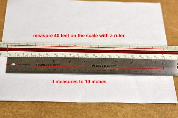
Finding the WANT
Take your architectural scale and find the 1/4 side and measure up to the 40 notch. This is how long we want that dimension to be. Now measure that to see how long that is in inches. Use your ruler, and hold it up to your scale, like you can see in the photo. In my case, it measures to exactly 10-inches.
Measure your desired dimension on with a ruler
Now we just have to do the math
10 inches (WANT) divided by 3.875 (IS) multiplied by 100 gives us 258.06%. This formula will get you very close, but you will want to print the sheet enlarged to that percentage and measure it with your architectural scale, and adjust up or down a percentage or two.
Take a measurement to see if you need to enlarge or reduce a bit to get it exact.
I have also made a chart so you can find the enlargement or reduction percentage to change the scale of a plan. Here is a scale factor chart, that might help you. Check out this link from Autodesk about resizing AutoCAD plans. I hope this helps you enlarge and reduce architectural drawings. If you have any questions, please contact us. If you would like any sheets converted to AutoCAD, send it over for a quick quote.
I am happy to be a part of the Del Mar Blue Print family! Even though I’ve only been there for a bit over a quarter of it’s 40 year history, I feel like I’ve been here for the whole time. Convert2AutoCAD has been here for around 2 years, and could not happen without the great support from Mike Kraus and the Del Mar Blue team. From a single person shop, to having over 20 employees and printing and shipping worldwide. Del Mar Blue Print has constantly been on the cutting edge of technology, while keeping it’s small family feel. Read a short history of the company at the Del Mar Blue Print blog.


You must be logged in to post a comment.